Sensor head installation, Top mount configuration) – MicroE OPS Series User Manual
Page 11
Page 11
Sensor Head Installation
(Top Mount Configuration)
OPS
™
Series Encoders
1.
Verify Sensor Mounting Surface Height
Refer to the OPS interface drawing for the latest dimensions.
Verify that the Z-height distance between the sensor mounting surface datum “A” and the top of the scale is as
follows:
Tape Scales:
Z-axis distance from top of tape scale after blue protective film is removed to Datum “A”
of sensor: 3.09 mm ±0.15
Z-Height Gauge (Model number ZG-PP1) can be used to verify proper Z-Height for PurePrecision Marker
Tape II and Laser Tape II scales
Glass Scales:
Z-axis distance from top of glass scale to Datum “A” of sensor: 2.93 mm ±0.15
Z-Height Gauge (Model Number ZG-GS1) can be used to verify proper Z-Height for PurePrecision
Performance and Value Linear Glass Scales
Use the correct gauge to check that there are no gaps between:
1.1 The mounting surface of the gauge and the mounting bracket, or
1.2 The bottom surface of the gauge and the scale.
Place the gauge in position and use the mounting screws as guides. If the bottom of the gauge hits the scale,
you will see the gap between the gauge bottom mounting surface and your mounting bracket surface.
If you hand tighten the sensor mounting screws, there should be no gap between the tape scale and the bottom
of the plastic gauge tool.
Z- Height Gauges
Tape Scales: P/N: ZG-PP1 (Black)
Glass Scales: P/N: ZG-GS1 (White)
Mounting bracket
surface
Scale top surface
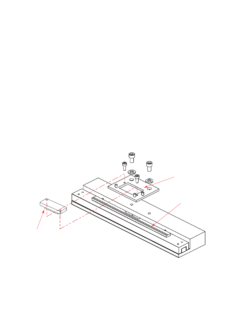
2.
Install Sensor
Install the sensor on the mounting surface referencing the appropriate datum surface as shown on the Interface
Drawing. Use two M2 or 2-56 screws to loosely affix the sensor.
A benching edge is recommended to locate the sensor to meet the mechanical mounting tolerances. Refer to the
Interface Drawing for recommended location and height of edge.