Sensor alignment – MicroE OPS Series User Manual
Page 16
Page 16
Sensor Alignment -
by SmartPrecision™ II Software
OPS
™
Series Encoders, Side and Top Mount Configurations
Connect the encoder to the Alignment Tool before connecting USB cable. Connect the USB cable to the
Alignment Tool
Run SmartPrecision II Software
1.
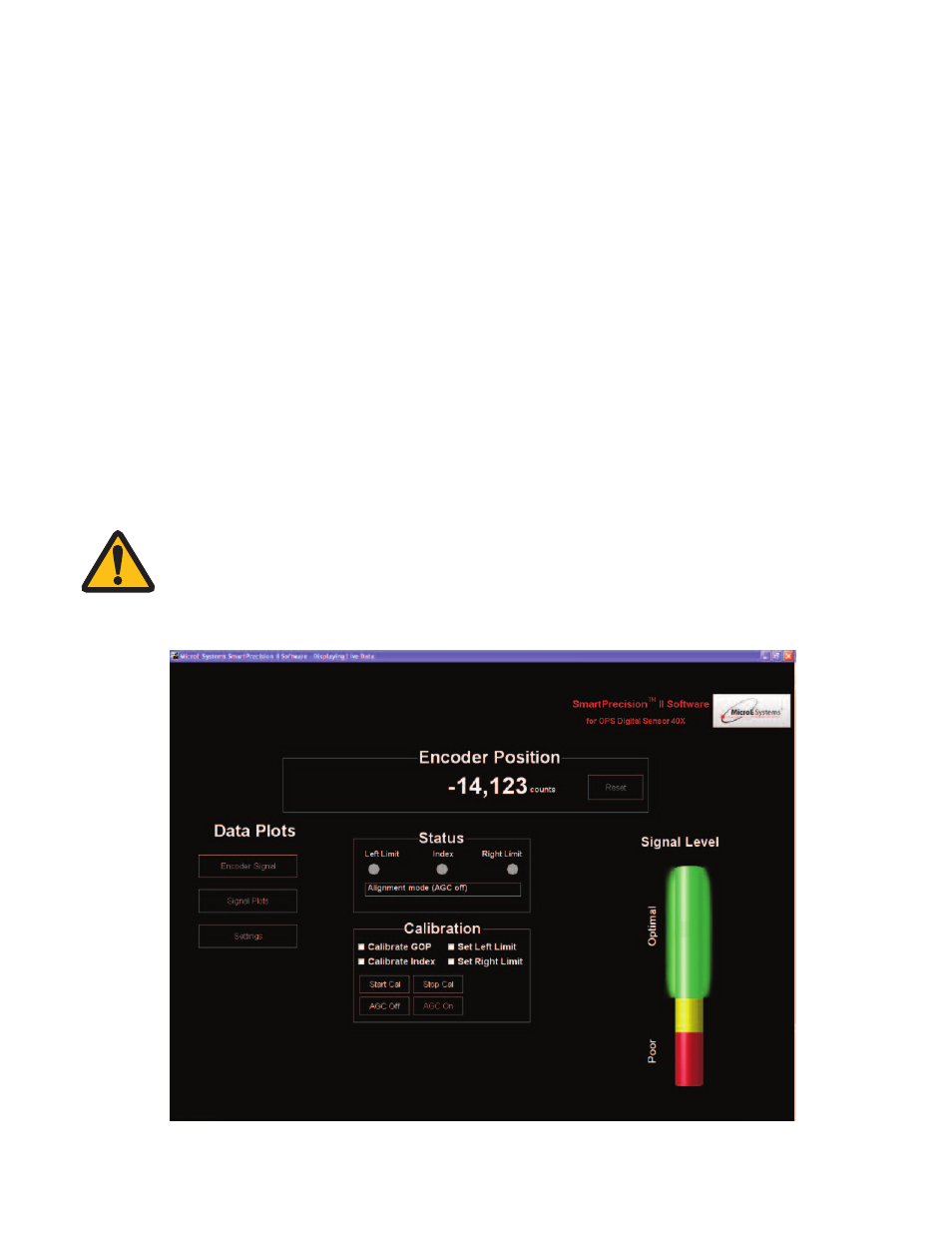
Align the sensor:
SmartPrecision II software automatically begins in Alignment Mode, with AGC off.
Position the sensor over a section of the scale. Adjust the sensor's Y or
q
z directions until the Signal
Level is in the Optimal Green level.
Move the sensor across the entire length of travel. The Signal Level should be in the Optimal Green level
over the entire length of travel. If the Signal Level is in the Yellow or Red areas, adjust Y and
q
z and refer
to the interface drawing to ensure proper mechanical design. (Passing over an Index will cause the
Alignment Tool Index/Limit LED to flash green.)
Check that Index LED blinks as sensor passes over index. Tighten sensor mounting screws.
Sensor LED Indicator Indicates signal strength – green for optimal performance, yellow for marginal
performance, and red for improper performance. Sensor LED will blink as sensor passes over index.
Alignment Mode is turned off automatically when you begin sensor calibration.
NOTE:
If you are having any difficulties getting a green light over the entire travel length, refer to the OPS
interface drawing to check mechanical design. Also, check to make sure the scale is properly
installed, the sensor is properly oriented with respect to the scale, and the blue protective film has
been removed from the tape scales.