Sensor calibration – MicroE OPS Series User Manual
Page 17
Page 17
Sensor Calibration -
by SmartPrecision™ II Software
OPS
™
Series Encoders, Side and Top Mount Configurations
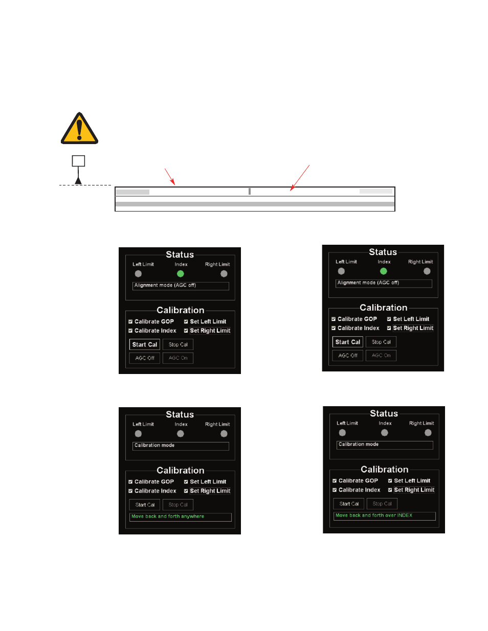
1.
Click appropriate
checkboxes before
calibrating:
Calibrate GOP
Calibrate Index
Set Left Limit
(optional)
Set right Limit
(optional)
Note: all procedures below must be performed at ≤1m/s relative motion between the sensor and
the scale.
3.
Move the sensor
back and forth
(Gain Offset
Phase).
NOTE:
Correct orientation of the scale for Left/Right Limit calibration is shown below. The
“D” datum edge from the OPS Interface Drawing is designated as the “Top” of the
scale. The Index/Limit track is also the “Top” track on a scale (tape and glass).
D
“D” datum edge of scale = “Top” of the scale.
Index/Limit Track
“Left” side of scale
“Right” side of scale
4.
Move the sensor
back and forth
over the Index
until the Left
Limit blue light
turns on. (The
Index is now
calibrated.)
2.
Click Start Cal
button.
Note: It is important that if you choose to calibrate only the limits, the sensor must be
placed in the “no limit” area of the scale (neither the left or right limit) when you click the
“Start Cal” button.