Sensor alignment/calibration, Using alignment tool, Sensor alignment – MicroE OPS Series User Manual
Page 12: By alignment tool, Series encoders, side and top mount configurations
Page 12
Sensor Alignment -
by Alignment Tool
OPS
™
Series Encoders, Side and Top Mount Configurations
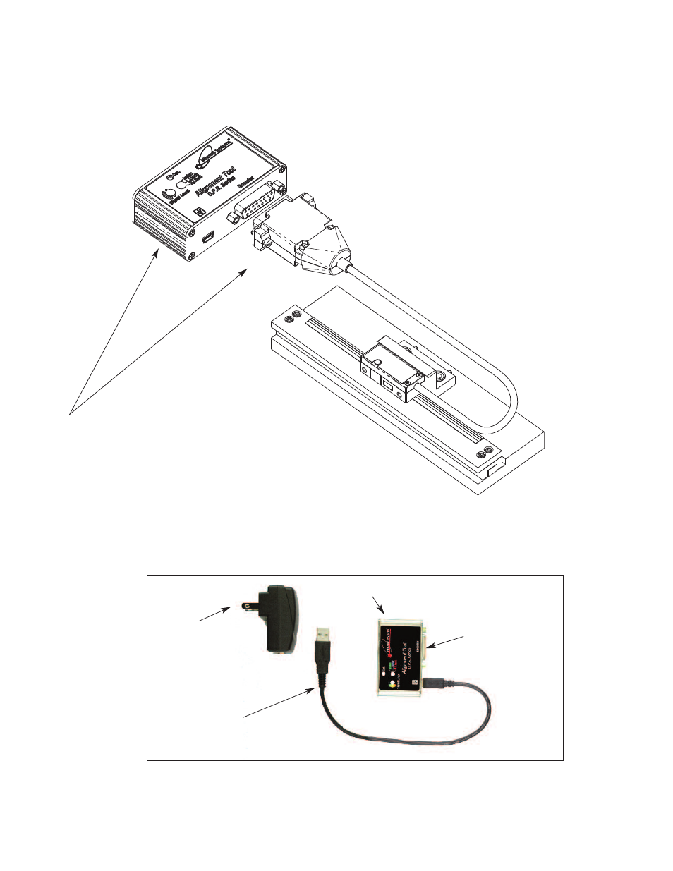
Be sure the source power is off before connecting the
SmartPrecision Alignment Tool to the sensor plug.
1.
Connect the encoder (either Side Mount or Top Mount) to the
SmartPrecision Alignment Tool.
Connect the USB cable to either a computer’s USB port or to
the DC power supply provided.
OPS Alignment Tool
Use Universal Power
supply with USB port for
Alignment Tool power if
not connecting to
computer USB port.
Mini USB computer interface cable
(plugs into either power supply or
computer)
To OPS Series
encoder sensor
OPS Alignment Tool
Sensor 15-pin D-Sub connector
(Side and top mount configurations;
side mount shown.)
OPS Alignment Tool kit, Model Number AT-OPS (Includes SmartPrecision II Software)