3 cio-quad connector diagram, D ifferential s ingle-e nded – Measurement Computing CIO-QUAD0x User Manual
Page 9
2.4 TESTING THE INSTALLATION
2.4.1 InstaCAL
Run the InstaCal program to test your board. Select the "Test" function of InstaCAL. This will run an internal test to assure
the base address has been properly set and the onboard registers are performing as expected. If the test fails, try
reconfiguring the board with a different Base Address. Once the board has been tested, select FILE then Exit, and the
configuration file will be written to your hard disk.
2.4.2 QUAD Encoder Demo Software
Included with your CIO-QUAD board is a floppy disk labeled QUAD ENCODER DEMO SOFTWARE. This disk contains
a demo program that allows you use many of the features of the CIO-QUAD without writing any code.
To install the demo software, insert the disk and run the SETUP.EXE program. Once installed, just double click the icon in
the QUADENC program group to run the program. You will be prompted to enter the board type and the base address you
selected above. Click OK after entering the appropriate values.
The main program screen allows to select the channels you wish to read and many configuration options for those channels.
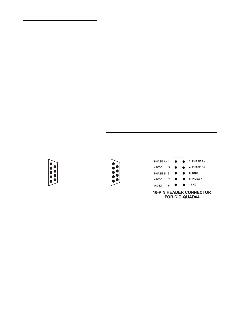
3 CIO-QUAD CONNECTOR DIAGRAM
Pin assignments for both differential and single-ended connections are shown in Figure 3-1 below. Be sure to properly
phase the encoder according to the manufacturer’s instructions.
Viewed from above
Figure 3-1. Connector Pin Outs for CIO-QUAD04
5
P has e A- 1
+ 5 V 2
P has e B - 3
+ 5 V 4
Index - 5
6 P has e A +
7 P has e B +
8 G N D
9 I ndex +
D ifferential
S ingle-E nded
G N D 1
+ 5 V 2
G N D 3
+ 5 V 4
G N D 5
6 P has e A +
7 P has e B +
8 G r ound
9 I ndex +
V iewed from the outs ide of the com puter look ing into the connectors on the board