Figure 1-1. functional block diagrams 2 – Measurement Computing CIO-QUAD0x User Manual
Page 6
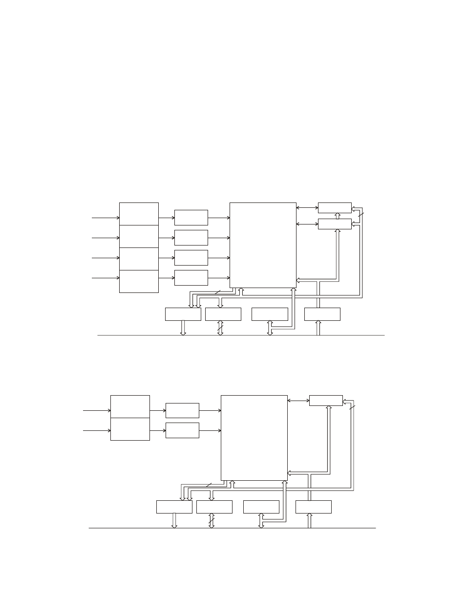
This component contains:
O
two, 24-bit counters
O
associated 24-bit preset and 24-bit output latch registers
O
integrated digital filtering with 8-bit counter prescalers
It provides:
O
programmable index functionality
O
programmable count modes including non-quadrature modes.
O
CIO-QUAD can also operate as a high-speed pulse and general purpose counter, cascadable to 96 bits. The 24-bit
counter can count either in binary or BCD through register selection.
The CIO-QUAD also includes an 8259 Programmable Interrupt Controller which accepts the four Index inputs directly and
the Carry/Borrow outputs from the LS7266 (counter overflow/underflow or count value match) to generate interrupts to the
PC bus. The interrupt controller operates in Polled Mode and allows for masking and priority setting of the interrupt inputs.
For an overall view of CIO-QUAD functionality, see the block diagrams in Figure 1-1 below.
8259 PIC
DATA
TRANSCEIVER
ADDRESS
DECODER
BUFFER
Channels
1&2
Channels
3&4
FPGA
Control
Decode
Signal Routing
Signalling
Signalling
CONTROL
CONTROL
ADDRESS
DATA
IRQ’S
S.E./Diff.
Setting
Termination
S.E./Diff.
Setting
Termination
S.E./Diff.
Setting
Termination
S.E./Diff.
Setting
Termination
Channel 1
Channel 2
Channel 3
Channel 4
QUADRATURE
ENCODER
INPUT
75ALS175
75ALS175
75ALS175
75ALS175
INTERRUPT
8
8
DATA BUS
LS7266: 24-Bit Dual-Axis
Quadrature Counter
ISA-BUS
CIO-QUAD04
Figure 1-1. Functional Block Diagrams
2
8259 PIC
DATA
TRANSCEIVER
ADDRESS
DECODER
BUFFER
Channels
1&2
FPGA
Control
Decode
Signal Routing
Signalling
CONTROL
CONTROL
ADDRESS
DATA
IRQ’S
S.E./Diff.
Setting
Termination
S.E./Diff.
Setting
Termination
Channel 1
Channel 2
QUADRATURE
ENCODER
INPUT
75ALS175
75ALS175
INTERRUPT
8
8
DATA BUS
LS7266: 24-Bit Dual-Axis
Quadrature Counter
ISA-BUS
CIO-QUAD02