Measurement Computing CIO-QUAD0x User Manual
Page 13
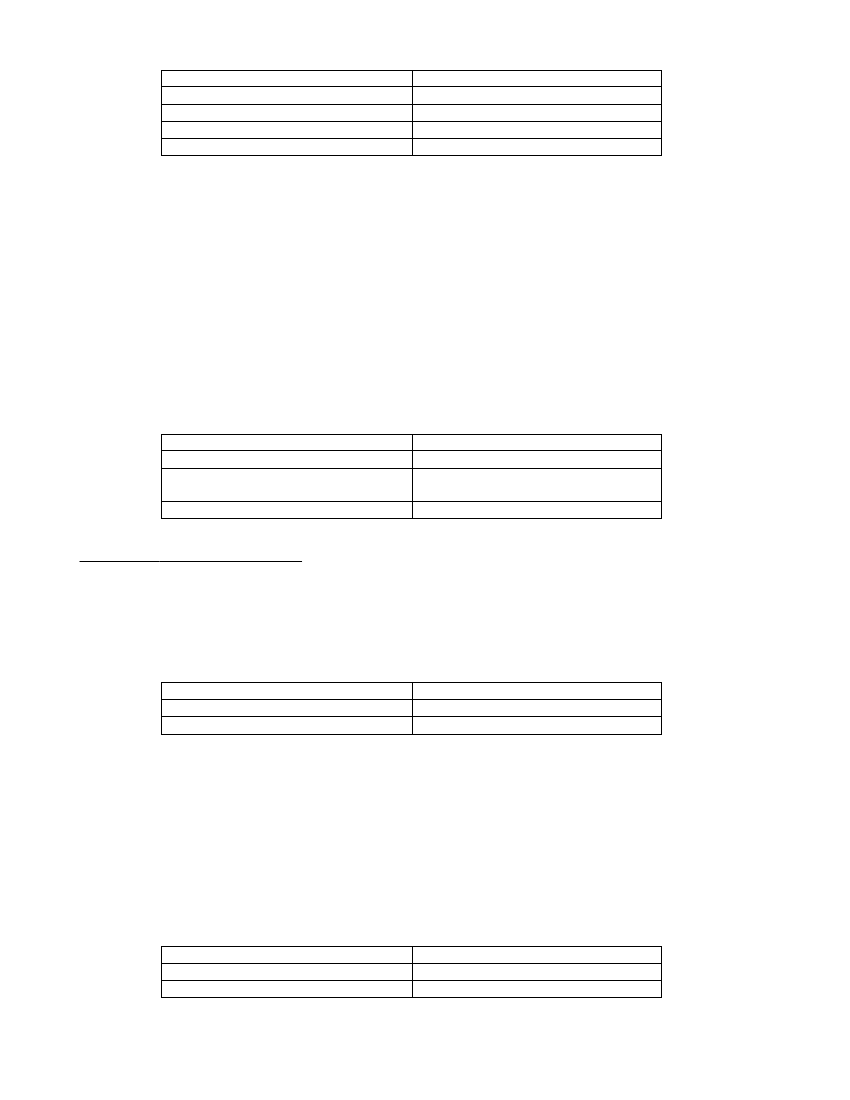
x01x x11x
Modulo-N
x01x x10x
Non-recycle
x01x x01x
Range-Limit
x01x x00x
Normal
Bit 1 & 2 value for mode selection
CMR Count Mode
Count Mode Definitions:
O
Range Limit: An upper limit, set by PR, and a lower limit, set to 0, are set. The CNTR stops at CNTR=PR when
counting UP and when CNTR=0 when counting DOWN. Counting resumed only when the count direction is reversed.
O
Non-Recycle: CNTR is disabled whenever an overflow or underflow happens. End-of-cycle marked by Carry (UP) or
Borrow (DOWN). Re-enabled by reset or load on CNTR.
O
Modulo-N: Count boundary set between 0 and content of PR. When counting up, at CNTR=PR, the CNTR is reset to
0 and the up count is continued from that point. When counting down, at CNTR=0, the CNTR is loaded with content
of PR and the down-count is continued from that point.
Quadrature scaling (bits 3 & 4)
There are four different scaling values that can be applied to quadrature signals: Non-quad, X1, X2, and X4. The scaling to
be applied is set in bits 3 & 4 (D3 and D4 - see Table 4-1) of the CMR register. Assuming the attached encoder generates
2500 pulses per revolution in X1 mode, then you would receive 5000 pulses in X2 mode and 10000 pulses in X4 mode. If
the board will be used to detect simple clock pulses then select Non-Quadrature mode.
x011 1xxx
X4
x011 0xxx
X2
x010 1xxx
X1
x010 0xxx
Non-Quadrature
Bit 3 & 4 value for quad scaling
CMR Quadrature Scaling
Input/Output Control Register (IOR)
The IOR register contains four user configurable fields and should be initialized prior to writing the IDR register which
follows. The IOR register, in conjunction with the IDR register, configures how the A and B input signals are interpreted.
A/B configuration bit (bit 0 - LSB)
This configuration bit (D0 - see Table 4-1) controls whether or not the A and B inputs are enabled or disabled. This bit must
be enabled for the counter to respond to input clock pulses.
x10x xxx1
Enable A and B
x10x xxx0
Disable A and B
Bit 0 value for enable/disable
IOR A/B enable/disable
LCNTR/LOL Pin Configuration (bit 1)
This register is only applicable if the IDR register bit 2 is reset to (0). In this case the Index input from the external encoder
is directed to the LCNTR/LOL pin. This bit (D1 - see Table 4-1) then configures the operation of the LCNTR/LOL pin. The
operation can be set to either load the counter with the preset value or load the output latch input. Thus, if the IDR register
specifies the Load CNTR operation, then each time the Index input is asserted, the counter will be reloaded with the value
stored in the preset. If the Load OL input option is selected, then each Index input will cause the current counter value to be
updated to the Output Latch. In this mode you are not required to use the RLD register to force the contents of the counter
to be copied to the output latch. The contents of the counter will automatically be available at the Output Latch every time
the Index signal is asserted.
Note: The Index input is asserted once per revolution.
x10x xx1x
Load OL input
x10x xx0x
Load CNTR
Bit 1 value for CNTR/LOL select
IOR LCNTR/LOL pin configuration
9