Measurement Computing CIO-QUAD0x User Manual
Page 14
RCNTR/ABG Pin Configuration (bit 2)
This bit (D2 - see Table 4-1) configures the operation of the RCNTR/ABG pin. This register in only applicable if the IDR
register, bit 2, is set to (1). In this mode, the Index input from the encoder is directed to the RCNTR/ABG input. The
operation can be configured to either reset the CNTR input or as an A/B enable gate.
Note: In non-quadrature mode, set this register for A/B enable gate operation.
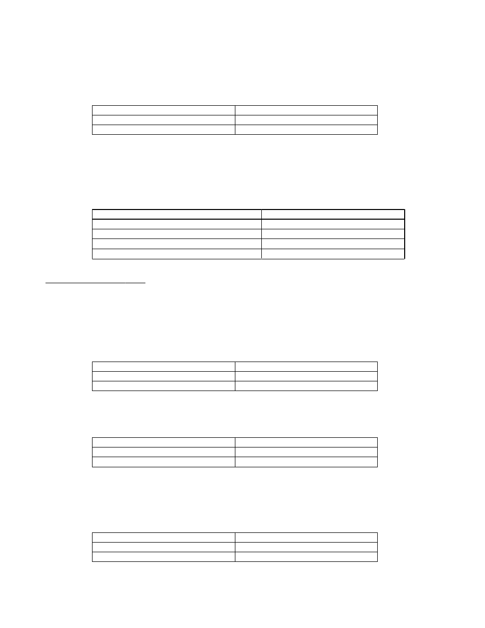
x10x x1xx
A/B enable gate
x10x x0xx
Reset CNTR
Bit 2 value for RCNTR/ABG select
IOR RCNTR/ABG pin configuration
FLAG 1 & 2 Configuration (bits 3 & 4)
This bit field (D3 and D4 - see Table 4-1) controls the operation of the FLG1 and FLG2 real-time counter outputs. The
selected configuration will determine what signal is output on the FLG1 and FLG2 output pins. For cascading the counters,
set this register for Carry/Borrow, Up/Down operation. The FLGx output pins are also redirected to the onboard 8259
Programmable Interrupt Controller (PIC). Depending on how the FLGx register is configured, an interrupt can be generated
based on the options in the following table.
x101 1xxx
FLG1 IDX, FLG2 is E
x101 0xxx
FLG1 Carry/Borrow, FLG2 U/D
x100 1xxx
FLG1 Compare, FLG2 Borrow
x100 0xxx
FLG1 Carry, FLG2 Borrow
Bit 3 & 4 value for FLG1/FLG2 select
IOR FLG1/FLG2 configuration
Index Control Register (IDR)
The IDR register controls how the Index input from the encoder is treated. It contains three user-configurable fields. The
polarity and Index routing selection are also made through this register.
Note: Disable indexing for non-quadrature inputs.
Enable/Disable Index (bit 0 - LSB)
This bit (D0 - see Table 4-1) is used to select whether or not indexing is enabled for the LS7266.
x11x xxx1
Enable Index
x11x xxx0
Disable Index
Bit 0 value for enable/disable select
IDR Index enable/disable
Index Polarity Select (bit 1)
If your are connecting a quadrature encoder, this bit (D1 - see Table 4-1) selects the polarity for the index: (0) for negative
polarity and (1) for positive polarity.
x11x xx1x
Positive Index Polarity
x11x xx0x
Negative Index Polarity
Bit 1 value for Index Polarity select
IDR Index Polarity
Index Pin Select (bit 2)
The final bit (D2 - see Table 4-1) in the IDR register determines where the index input will be connected. A bit value of (0)
selects the LCNTR/LOL pin as the connection for the encoder index output. If the bit is set to (1), the RCNTR/ABG pin is
selected as the index input. Prior to configuring this bit, configure the IOR register, bit 1 or 2. See the previous section for
more details on these bit fields.
x11x x1xx
RCNTR/ABG pin is indexed
x11x x0xx
LCNTR/LOL pin is indexed
Bit 2 value for Index Pin select
IDR Index Pin Select
10