A/d stop signal, Waveform generation timing connections, D/a start trigger signal – Measurement Computing PCI-DAS6023 User Manual
Page 25: Figure 16
PCI-DAS6023 and PCI-DAS6025 User's Guide
Functional Details
25
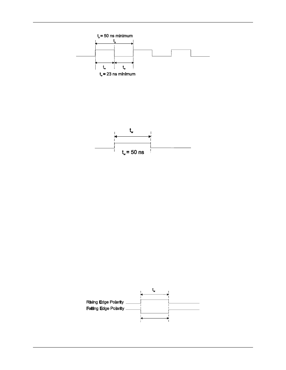
Figure 16. A/D EXTERNAL TIME BASE signal timing
A/D STOP signal
The A/D STOP signal indicates a completed acquisition sequence. You can program this signal to be available
at any of the AUXOUT pins. The A/D STOP output signal is a 50 ns wide pulse whose leading edge indicates a
DAQ done condition.
Figure 17. A/D STOP signal timing
Waveform generation timing connections
There are three signals that control the timing for the analog output functions on the PCI-DAS6025. These are
D/A START TRIGGER, D/A UPDATE, and D/A EXTERNAL TIME BASE signals.
D/A START TRIGGER signal
The D/A START TRIGGER signal is used to hold off output scans until after a trigger event. The DAQ-Sync
―DS D/A START TRIGGER‖ input or any AUXIN pin can be programmed to serve as the D/A START
TRIGGER signal. It is also available as an output on any AUXOUT pin.
When used as an input, the D/A START TRIGGER signal may be software selected as either a positive or
negative edge trigger. The selected edge of the D/A START TRIGGER signal causes the DACs to start
generating the output waveform.
The D/A START TRIGGER signal can be used as an output to monitor the trigger that initiates waveform
generation. The output is an active-high pulse having a width of 50 ns.
Figure 18 and Figure 19 show the input and output timing requirements for the D/A START TRIGGER signal.
t
w
= 37.5 ns
minimum
Figure 18. D/A START TRIGGER input signal timing