Daq-sync connector and pinout, Field wiring and signal termination accessories, Figure 3 – Measurement Computing PCI-DAS6023 User Manual
Page 16
PCI-DAS6023 and PCI-DAS6025 User's Guide
Installing the PCI-DAS6023 or PCI-DAS6025
16
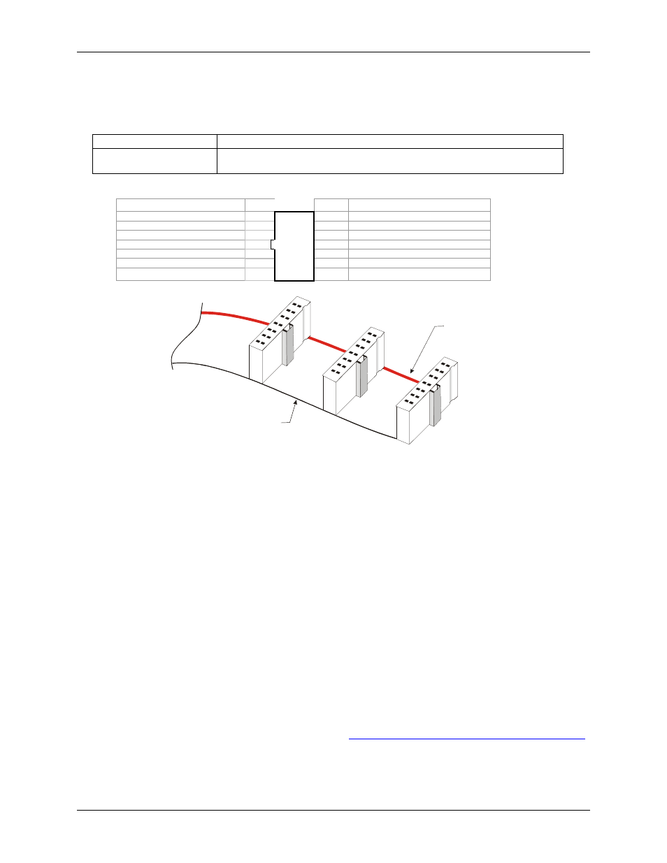
DAQ-Sync connector and pinout
DAQ-sync connector & cable types
Connector type
14-pin right-angle 100mil box header
Compatible cables
MCC p/n: CDS-14-x, 14 pin ribbon cable for board-to board DAQ-sync connection;
x = number of boards (from 2 to 5 boards can be connected). See Figure 3.
DAQ-sync connector pinout (view from top)
Signal Name
Pin
Pin
Signal Name
DS A/D START TRIGGER
1 ■
■ 2
GND
DS A/D STOP TRIGGER
3 ■
■ 4
GND
DS A/D CONVERT
5 ■
■ 6
GND
DS D/A UPDATE
7 ■
■ 8
GND
DS D/A START TRIGGER
9 ■
■ 10
GND
RESERVED
11 ■
■ 12
GND
SYNC CLK
13 ■ ■ 14
GND
14-pin Ribbon Cable
The red stripe
identifies pin # 1
14
2
1
13
14
2
1
13
14
2
1
13
Figure 3. CDS-14-3 cable
Field wiring and signal termination accessories
The following Measurement Computing accessory boards can be used with the PCI-DAS6023 and PCI-
DAS6025:
Screw terminal boards and BNC adapters
Use with the C100HD50-x cable:
BNC-16SE – Brings analog signals to standard BNC connectors. Designed for boards operating in single-
ended mode.
BNC-16DI – Brings analog signals to standard BNC connectors. Designed for boards operating in
differential mode.
CIO-MINI50 – 50-pin screw terminal board. Two boards are required.
CIO-TERM100 – 100-pin screw terminal board (daisy-chained 50-pin IDC connectors).
SCB-50 – signal connection box, 50 conductor, shielded.
Use with the C100MMS-x cable:
SCB-100 – signal connection box, 100 conductor, shielded.
Details on these products are available on our web sit