Measurement Computing CIO-DAS16/M1 User Manual
Page 8
4
3.
SIGNAL CONNECTIONS
3.1
INTRODUCTION
There are three connectors on th CIO-DAS16/M1. The 37-pin connector, P1, on the rear mounting plate is
primarily for analog signals. It is referred to as the analog connector. The 40-pin header connector, P5, at
the front of the board has 24 digital I/O lines. It also has clock, gate, and output signals for three counters
associated with registers Base + 404, +405, and +406. It is referred to as the digital connector.
The DT-Connect connector (P4) at the top of the board is included primarily for use with the MEGA-
FIFO huge sample buffer, which may be required to attain the maximum acquisition rate.
3.2
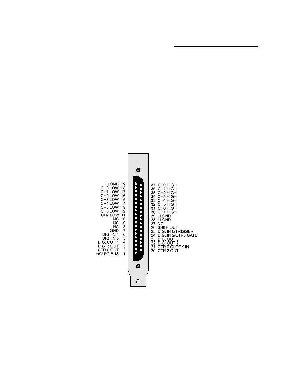
ANALOG CONNECTOR DIAGRAM
The CIO-DAS16/M1 analog connector is a 37-pin, D-type connector accessible from the rear of the PC
on the expansion backplate. The connector accepts female 37-pin D-type connectors, such as the C37FF-
2, a 2-foot cable. The Counter 0 signals are associated with the register at Base + C.
The CTR 2 OUT signal is the internal PACER signal (registers at Base + D, +E, and +F.)
Figure 3-1. Analog Connector Pin Out
If frequent changes to signal connections or signal conditioning is required, please refer to the information
on the CIO-MINI37, CIO-TERMINAL, or SCB-37 screw terminal board.