Measurement Computing CIO-DAS16/M1 User Manual
Page 20
16
READ
The signals present at the inputs are read as one byte, the most significant four bits of which are always
zero. The pins 25 (DIN 0) and 24 (DIN 2) digital inputs have two functions each.
The TRIG function of DIN 0 can be used to hold off the first sample of an A/D set by holding it low (0V)
until you are ready to take samples, which are then paced by the 8254. It can also be used as the source of
an external start conversion pulse, synchronizing A/D conversions to some external event.
The DIN 2 (pin 24) can be used as a GATE input to counter 0, the externally-accessible user configurable
counter of U43 (82C54). For CTR0 to operate, DIN 2 must be held high or left floating. Holding it low
will hold off inputs to the CTR0 CLOCK input.
When written to:
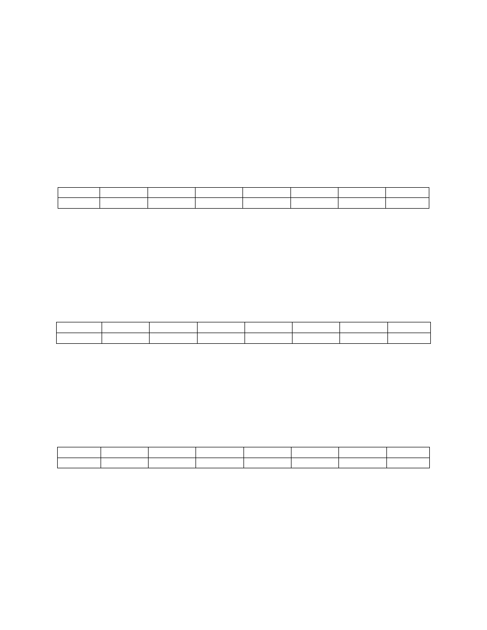
7
6
5
4
3
2
1
0
X
X
X
X
DO3
DO2
DO1
DO0
WRITE
The upper four bits are ignored. The lower four bits are latched TTL outputs. After written, the state of
the outputs cannot be read back because a read back would read the separate digital input lines (see
above).
4.6.4
Clear Interrupt Status R egister
BASE ADDRESS + 4
7
6
5
4
3
2
1
0
X
X
X
X
X
X
X
X
A WRITE ONLY REGISTER
Write any value to this register to clear IRQDATA, the interrupt status bit at BASE + 2.
4.6.5
Interrupt Control, Pacer Source Register
BASE ADDRESS + 5
7
6
5
4
3
2
1
0
INTEN
L2
L1
L0
SPARE3
SPARE2
S1
S0
INTEN: Interrupt enable. Set to 1 it allows interrupts to pass from the CIO-DAS16/M1 interrupt flip flop
to the PC system bus. Set to 0, no interrupts are passed to the PC system bus regardless of other settings.