Measurement Computing CIO-DAS16/M1 User Manual
Page 23
19
Decimal codes are for upper four bits only. In other words, this is the correct byte to write if the channel
is equal to zero. Channel values can be 0 to 8 (differential) The code to write an input range of ±2.5V on
channel 7 would be 16 + 7 = 23.
4.6.8
Total Counter Data & C ontrol Registers
The 82C54 counter chip is quite complex. The data sheet for the part contains programming information,
input and output timing diagrams and interfacing specifications.
It is beyond the scope of this manual to reproduce the information, all of which is contained in the
manufacturers data sheet. That data sheet can be obtained from the Intel or Harris web page.
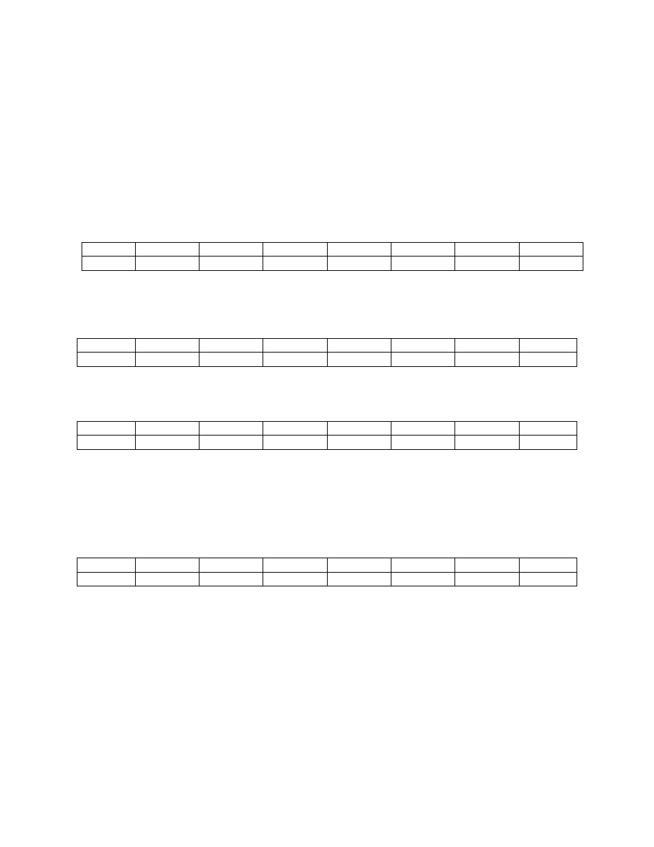
8254 COUNTER 0 DATA - Total counter upper 1/2
BASE ADDRESS + 8
7
6
5
4
3
2
1
0
D8
D7
D6
D5
D4
D3
D2
D1
8254 COUNTER 1 DATA - Total Counter lower 1/2
BASE ADDRESS + 9
7
6
5
4
3
2
1
0
D8
D7
D6
D5
D4
D3
D2
D1
8254 COUNTER 2 DATA - Pre-trigger index counter
BASE ADDRESS + A
7
6
5
4
3
2
1
0
D8
D7
D6
D5
D4
D3
D2
D1
The three 8254 counter/timer data registers can be written to and read from. Because each counter will
count as high as 65,536, it is clear that loading or reading the counter data must be a multi-step process.
The operation of the 8254 is explained in the section on the counter/time and the Intel 8254 data sheet.
8254 COUNTER CONTROL
BASE ADDRESS + B
7
6
5
4
3
2
1
0
D8
D7
D6
D5
D4
D3
D2
D1
This register controls operation and loading/reading of the counters. The configuration of the 8254 codes
which control the 8254 chip is explained in the section on the counter timer and the Intel 8254 data sheet.