Measurement Computing CIO-DAS16/M1 User Manual
Page 18
14
4.6.1
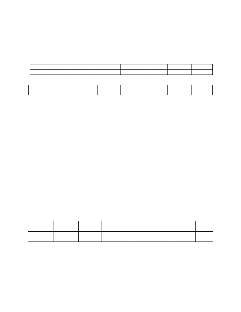
A/D Data & Channel Re gisters
Note: Although the bus interface is 16 bits wide, only the A/D data and channel registers should be read
as a 16-bit word (pair). The register at BASE + 1 can only be read as the most significant 8 bits of a 16-bit
read to BASE + 0. There is no decoding to access the BASE + 1 register as a byte. All other registers
BASE + 2 to BASE + F must be read as bytes.
BASE ADDRESS + 0
7
6
5
4
3
2
1
0
A/D9
A/D10
A/D11
A/D12 LSB
CH8
CH4
CH2
CH1
BASE ADDRESS + 1
7
6
5
4
3
2
1
0
A/D1 MSB
A/D2
A/D3
A/D4
A/D5
A/D6
A/D7
A/D8
NOTE: BASE ADDRESS + 0 and BASE ADDRESS + 1 must be read as a single 16-bit word
Read/Write Registers
READ
On read, it contains two types of data; analog input data and the channel
number of the current data.
The A/D data is in the format: 0 = minus full scale; 4095 = +FS.
The channel number is in binary. The weights are shown in the table above. If the current channel is 5,
bits CH4 and CH1 would be high and CH8 and CH2 would be low.
WRITE
Writing any data to the Base + 0 register causes an immediate A/D conversion.
NOTE: Do not initiate A/D conversions prior to loading the channel/gain queue.
4.6.2
Control & Status Bits
BASE ADDRESS + 2
7
6
5
4
3
2
1
0
IRQDATA
R/O
TRGSTAT
R/O
OVRUN
R/O
TOOFAST
R/W
PRETRIG
R/W
DTEN
R/W
CTR0
R/W
TRIG0
R/W
IRQDATA: This bit is the status of the IRQ flip flop. It does not require that interrupts be enabled. It is
cleared by writing any data to BASE + 4.