Simple voltage divider – Measurement Computing CIO-DAS16/M1 User Manual
Page 35
31
The sum of the voltage drops around a circuit is equal to the voltage drop for the entire circuit.
Implied in the above is that any variation in the voltage drop for the circuit as a whole will have a
proportional variation in all the voltage drops in the circuit. In a voltage divider, the voltage across one of
the resistors in a circuit is proportional to the ratio of the resistor to the total resistance in the circuit.
In a voltage divider, you must choose two resistors with the proper proportions relative to the full scale of
the analog or digital input and the maximum signal voltage.
SIGNAL HIGH
SIGNAL LOW
R1
R2
A/D BOARD
HIGH INPUT
A/D BOARD
LOW INPUT
SIGNAL
VOLTS
V1
V2
Vout
Vin
=
R1 + R2
R2
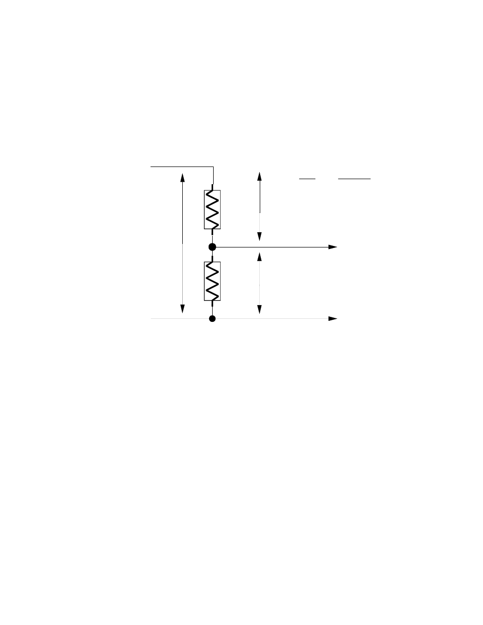
SIMPLE VOLTAGE DIVIDER
Vin
Vout
Figure 6-3. Voltage Divider
The formula for attenuation is:
Attenuation = R1 + R2 / R2
Attenuation is the proportional difference between the signal voltage max and the full scale of the analog
input.
For example, if the signal varies between 0 and 20 volts and you wish to measure that with an analog
input with a full scale range of 0 to 10 volts, the Attenuation is 2:1 or just 2.
R1 = (A-1) * R2 For a given attenuation, pick a handy resistor, call it R2, then use this formula to
calculate R1.
Digital inputs also make use of voltage dividers, for example, if you wish to measure a digital signal that
is at 0 volts when off and 24 volts when on, you cannot connect that directly to digital inputs. The voltage
must be dropped to 5 volts maximum when on. The Attenuation is 24:5 or 4.8. Use the equation above to
find an appropriate R1 if R2 is 1K. Remember that a TTL input is 'on' when the input voltage is greater
than 2.5 volts.
IMPORTANT NOTE: The resistors, R1 and R2, are going to dissipate all the power in the divider circuit
according to the equation Current = Voltage / Resistance. The higher the value of the resistance (R1 + R2)
the less power dissipated by the divider circuit. We suggest:
For attenuation of 5:1 or less, no resistor should be less than 10K.
For attenuation of greater than 5:1, no resistor should be less than 1K.
The CIO-TERMINAL has breadboard solder points on board to create custom voltage dividers. The CIO-
TERMINAL is a 16" by 4" screw terminal board with two 37 pin D type connectors and 56 screw