Counter input, Frequency input measurement, Counter input -5 – Measurement Computing CB-7080 User Manual
Page 9: Frequency input measurement -5
CB-7080 & CB-7080D Counter/Timer User's Guide
Application wiring
1-5
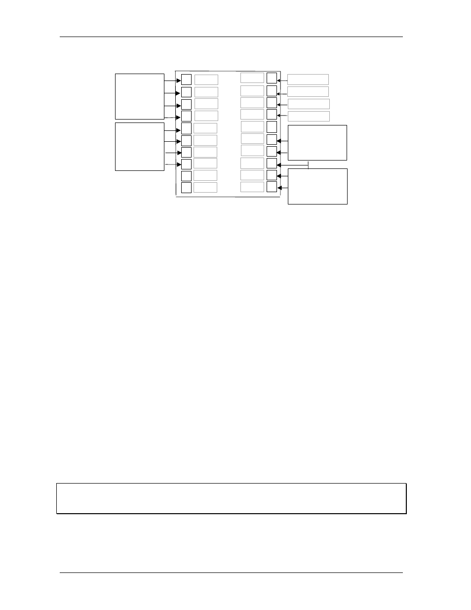
Counter input
Ext. GND
Ext. 24V
RS-485 Data-
RS-485 Data-
7
6
5
4
3
8
2
1
9
10
GND
+VS
Data+
Data-
In0
D.Gnd
Gate0
Init*
12
11
Gate1-
Gate1+
143
15-
16
17
18
13
19
20
In1-
Do1/Hi
Do0/Lo
In0+
Gate1
In1
In1+
Gate0-
Gate0+
In0-
CB-7080 & CB-7080D
Counter-1
Input 1 & Gate-1
(isolated)
Counter-0
Input 0 & Gate-0
(isolated)
Counter-1 & Gate-1
(non-isolated)
Counter-0 & Gate-0
(non-isolated)
Figure 1-5. Counter input
Frequency input measurement
Perform the following procedure to measure the frequency input of each channel. Refer to Figure 1-4 for the
wire connection.
1. Power on and run the test.exe application.
2. Press 2
3. Press $012[Enter]
Receive=!01500600
4. Press 2
5. Press %0101510600[Enter]
Receive=>!01
6. Press 2
7. Press $01B0[Enter]
Receive=!01
8. Press 2
9. Press #010[Enter]
Receive=>????????
10. Press 2
11. Press #011[Enter]
Receive=>????????
In step 3: the status of CB-7080 is COUNTER mode.
In step 5: Change to frequency mode.
In step 7: Select non-isolated input.
In step 9: Frequency measurement of channel-0.
In step 11: Frequency measurement of channel-1.
Note
The command $01B1 that is referenced in step 7 can be used to select the isolated input. The commands
$01B2 and $01B3 are used for the other selections.