Digital output, Power, Power consumption – Measurement Computing CB-7080 User Manual
Page 7: Functional block diagram, Digital output -3, Power -3, Power consumption -3, Functional block diagram -3
CB-7080 & CB-7080D Counter/Timer User's Guide
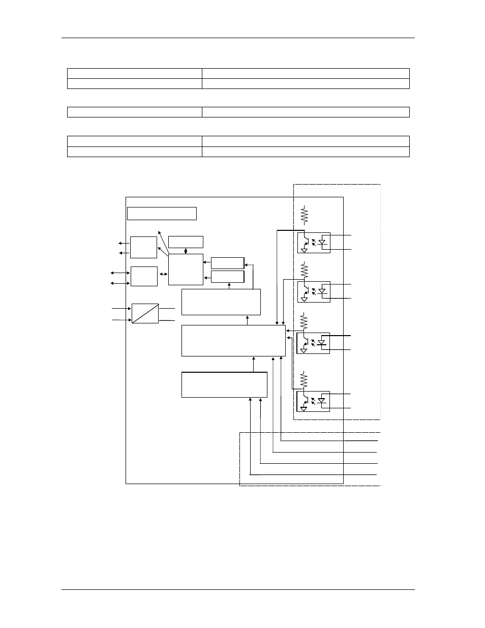
Functional block diagram
1-3
Digital output
Capacity
2 channels, open-collector to 30 V, 30 mA max load
Power Dissipation
300 mW
Power
Power Requirements
+10V to 30V (non-regulated)
Power consumption
CB-7080
2.0 W
CB-7080D
2.2 W
Functional block diagram
Embedded
Controller
Programmable Digital Filter
EEPROM
RS-485
D+
D-
DC
DC
V+
V-
5V
0V
D/O
O.C.
Alarm
Output
5-digit LED (CB-7080D)
5V
Counter_0
Counter_1
5V
Gate0+
Isolated/Non-isolated input selection
Isolated/Non-isolated gate selection
Gate0-
5V
Gate1+
Gate1-
In0+
In0-
In1+
In1-
Gate0(TTL)
Gate1(TTL)
In0(TTL)
In1(TTL)
Programmable threshold voltage
Non-isolated inputs
Isolated inputs
5V
Figure 1-2. CB-7080D Block Diagram
This manual is related to the following products: