Pin assignments, Specifications, Frequency measurement – Measurement Computing CB-7080 User Manual
Page 6: Pin assignments -2, Specifications -2, Frequency measurement -2
CB-7080 & CB-7080D Counter/Timer User's Guide
Pin assignments
1-2
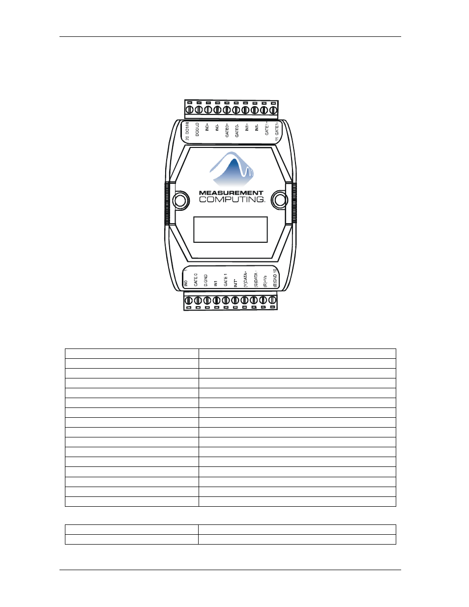
Pin assignments
The pin names and locations on the CB-7080D module are shown in Figure 1-1.
CB-7080D
Figure 1-1. CB-7080D pin identification
Specifications
CB-7080
Counter/Frequency Module
CB-7080D
CB-7080 with LED Display
Counter Input Channels
Two independent 32 bit counters, counter 0 and 1.
Input signal
Isolated or non-isolated programmable
Isolation input levels:
Logic level 0
+1 V max
Logic level 1
+3.5 V to +30 V
Isolation voltage
3750 V RMS
Non-isolation input threshold level:
Programmable
Logic level 0
0 to +5 V (default = 0.8 V)
Logic level 1
0 to +5 V (default = 2.4 V)
Maximum count
32 bit (4,294,967,295)
Programmable digital noise filter
2
s to 65 ms
Alarming
alarm on counter 0 or counter 0 and 1, programmable
Counter preset value
Programmable
Display LED Indicator
5-digit read out, channel 0 or channel 1
Frequency measurement
Input frequency
1 Hz to 100 kHz max
Programmable built-in gate time
1.0 or 0.1 sec