Power in jumper (jp1), I/o module type selection (jp2, jp3), I/o module polarity selection (jp5, jp6) – Measurement Computing 6K-SSR-RACK08 User Manual
Page 27: Bypass resistors, Compatible products, Power in jumper (jp1) -2, I/o module type selection (jp2, jp3) -2, I/o module polarity selection (jp5, jp6) -2, Bypass resistors -2, Compatible products -2
6K-SSR-RACK08 User's Guide
Specifications
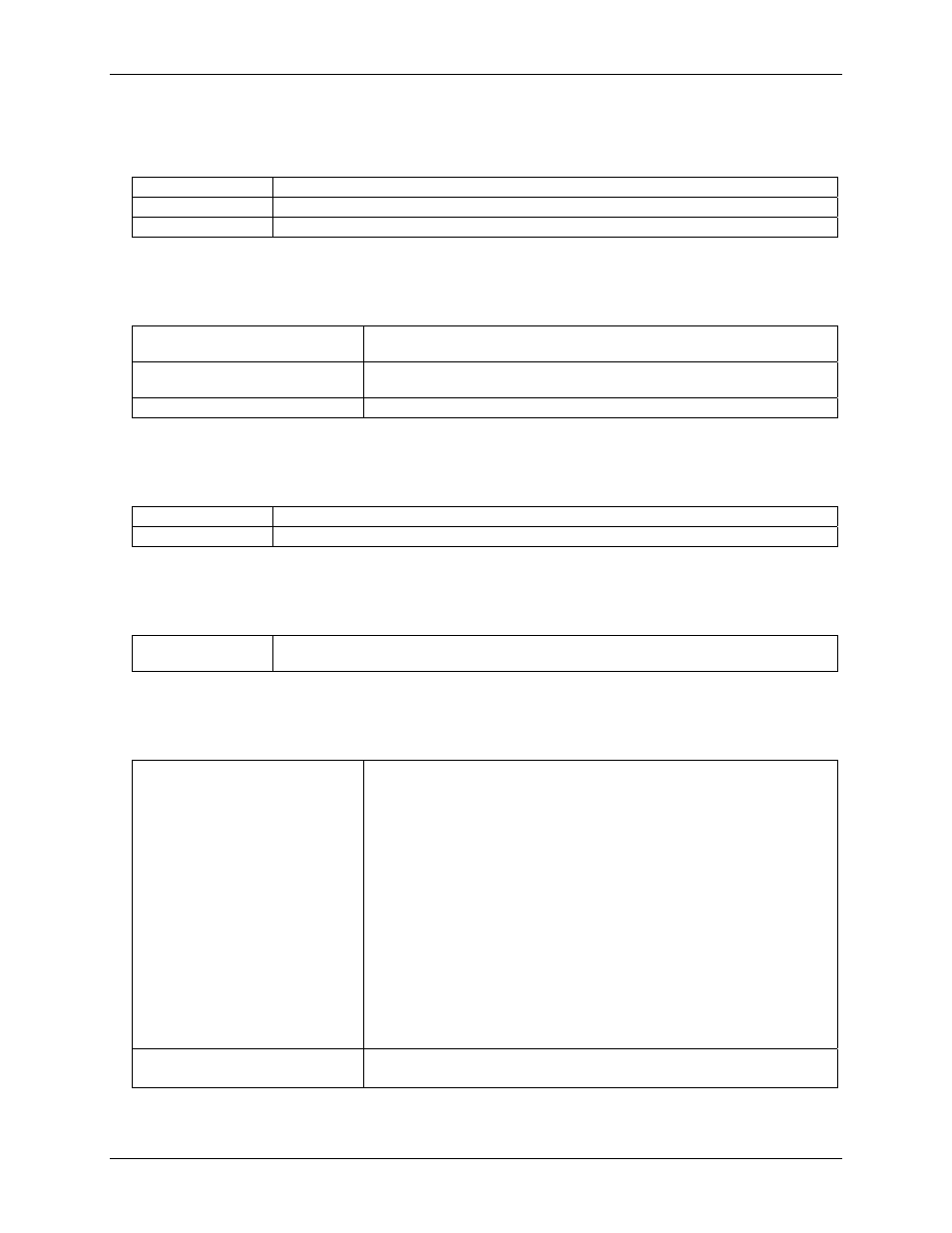
Power in jumper (JP1)
Table 6. JP1 specifications
+5PC
Use cable C-PCPOWER-10
+9V EXT
Use Adapter CB-PWR-9
+5 BD (default)
Powered from 100-pin connector
I/O module type selection (JP2, JP3)
Table 7. JP2 and JP3 specifications
Modules 1-4
Selectable via JP2 as either input modules or output (default) modules. Do not
mix input and output modules within this bank of four.
Modules 5-8
Selectable via JP3 as either input modules or output (default) modules. Do not
mix input and output modules within this bank of four.
Pull-up/pull-down on digital I/O lines
Configurable at RN1 with 2.2 K resistor network. Not populated by default.
I/O module polarity selection (JP5, JP6)
Table 8. JP5 and JP6 specifications
Modules 1-4
Inverted (active high) or non-inverted (active low, default), selectable via JP5.
Modules 5-8
Inverted (active high) or non-inverted (active low, default), selectable via JP6.
Bypass resistors
Table 9. Bypass resistor specifications
Resistors R1 – R8
(Normally 0 Ω)
Transceiver bypass resistors for bit-wise I/O configuration. NOT populated by default. Bypass
resistors are mutually exclusive of 74LS245 and 74LS640 transceivers.
Compatible products
Table 10. Compatible product specifications
Analog input boards
PCI-DAS6013
PCI-DAS6014
PCI-DAS6030
PCI-DAS6031
PCI-DAS6032
PCI-DAS6033
PCI-DAS6034
PCI-DAS6035
PCI-DAS6036
PCI-DAS6052
PCI-DAS6023
PCI-DAS6025
PCI-DAS6040
PCI-DAS6070
PCI-DAS6071
Analog output boards
PCI-DAC6702
PCI-DAC6703
Note 1:
The 6K-SSR-RACK08 requires external power (for all products above) when used with the
C100HD50 (pins 51-100) ribbon cable.
4-2