External +9v ac adapter power connection, I/o type, Relay logic – Measurement Computing 6K-SSR-RACK08 User Manual
Page 19: I/o type -10, Relay logic -10
6K-SSR-RACK08 User's Guide
Installing the 6K-SSR-RACK08
3. Run the power cable out the back of the computer through an expansion slot or other opening, and replace
the cover on the computer.
Caution!
Be careful not to pinch the cable when you replace the cover — if this cable is cut, the resulting
short circuit can damage the computer.
4.
5.
1.
2.
3.
4.
Connect the other end of the power cord to the connector labeled
PC POWER
connector (
P14
) on the 6K-
SSR-RACK08. Refer to
for the location of this connector.
Set the
POWER IN
jumper (
JP1
) for
+5PC
.
External +9V AC adapter power connection
You can power the 6K-SSR-RACK08 using the AC power adapter (part number CB-PWR-9). This adapter
provides 9 volts, 1 amp DC power, 110 VAC power. To connect the AC adapter, do the following:
Turn off power to the computer.
Connect the CB-PWR-9 cable to the
9V EXTERNAL POWER
connector (
P13
) on the 6K-SSR-RACK08.
Refer to
for the location of this connector.
Plug the AC adapter into a power outlet.
Set the
POWER IN
jumper (
JP1
) for
9V EXT
.
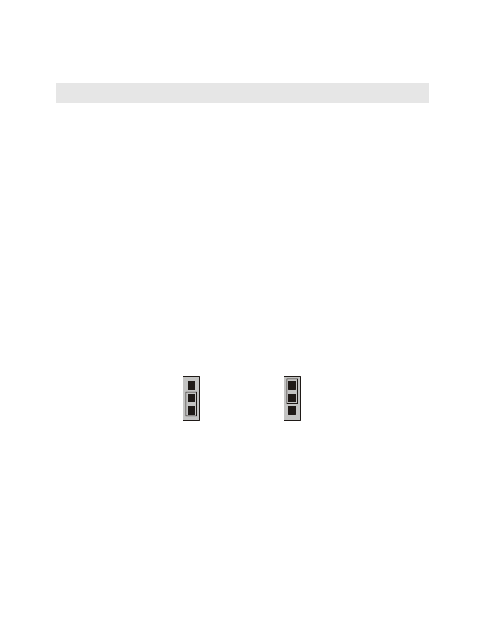
I/O type
Set the type for each module group for either input or output (default). You cannot mix the I/O configuration
within a group.
Jumper
JP2
sets the I/O type for SSR modules 1-4
Jumper
JP3
set the I/O type for SSR modules 5-8.
Refer to
for the location of these jumpers.
shows the SSR modules 1-4 configured for
input (jumper position 2-3), and SSR modules 5-8 configured for output (jumper position 1-2).
Figure 2-6. I/O module type jumpers
JP2
1
2
3
OUT
IN
JP3
1
2
3
OUT
IN
SSR modules 1-4
configured for input
SSR modules 5-8
configured for output
Relay logic
Set the relay logic for each module group to be either inverted (active high) or non-inverted (active low,
default). Jumper
JP5
sets the logic for SSR modules 1 to 4. Jumper
JP6
sets the relay logic for SSR modules 5
to 8. The logic settings are labeled
INVERT
and
NON
-
INVERT
on the board.
When you set the logic jumper to NON-INVERT, the SSR modules activate when the digital output signal
is low.
When you set the logic jumper to INVERT, the SSR modules activate when the digital output signal is
high.
2-10