Led states, Led states -4, 4 for – Measurement Computing 6K-SSR-RACK08 User Manual
Page 24: Gure 3-4
6K-SSR-RACK08 User's Guide
Functional Details
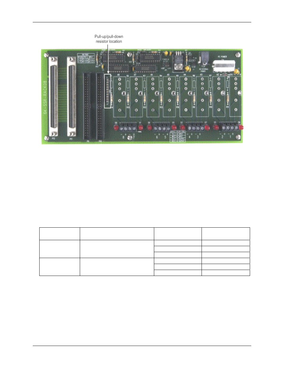
Figure 3-4. SIP resistor location
To pull up the digital line for a particular port, install the resistor with the common line at the
HI
end. To pull
down a digital line, install the resistor with the common line at the
LO
end. The SIP establishes a high or low
logic level at each digital I/O line when disconnected from the 6000 Series control board or when the digital
lines on the 6000 Series control board are in high impedance (or input) mode.
When the 6K-SSR-RACK08 is disconnected from the 6000 Series control board or when the digital lines on the
6000 Series control board are in high impedance (or input) mode, the solid state relays are undriven. The state
of the solid state relays when not driven is dependent on the invert/non-invert logic jumper setting and the pull-
up/pull-down resistor configuration.
summarizes the undriven state of the SSR output modules for
each configuration.
Table 3-1. SSR output module power up and reset conditions
I/O type
Logic jumper setting
Pull-up / down
installed
Power up / reset
state
none
high state = on
pull-up
high state = on
output
invert (logic high)
pull-down
high state = off
none
low state = on
pull-up
low state = off
output
non-invert (logic low)
pull-down
low state = on
LED states
The LEDs indicate the on/off status of the SSR modules. The LED illuminates when an output module is active
(turned on) or when an input module detects an input voltage (logic high).
3-4