Compatible ssr modules, Screw terminal connections, Wire gauge – Measurement Computing 6K-SSR-RACK08 User Manual
Page 23: Signal level control and power up conditions, Compatible ssr modules -3, Screw terminal connections -3, Wire gauge -3, Signal level control and power up conditions -3
6K-SSR-RACK08 User's Guide
Functional Details
Compatible SSR modules
The 6K-SSR-RACK08 board has locations for eight solid state relay modules that you can install in your 6K-
SSR-RACK08 board. The SSR modules use a standard color scheme so you can quickly identify what module
type is installed. Mounting screw threads are provided for you to easily install the SSR modules.
MCC offers SSR modules that are compatible with the 6K-SSR-RACK08:
SSR-IAC-05
SSR-OAC-05A
SSR-IAC-05A
SSR-ODC-05
SSR-IDC-05
SSR-ODC-05A
SSR-IDC-05NP
SSR-ODC-05R
SSR-OAC-05
Details on these SSR modules are available from our web site at
.
Screw terminal connections
Use the board's screw terminals to connect external devices to the SSR modules. Two terminals are dedicated to
each module (one positive and one negative terminal).
Caution!
Before connecting wires to the screw terminals, turn off the power to the 6K-SSR-RACK08, and
make sure that the signal wires do not contain live voltages.
Wire gauge
Use 12 AWG to 22 AWG wire to connect field devices. Properly insulate the wires to avoid any short circuit to
the other channels, ground, or other points on the board.
Signal level control and power up conditions
To ensure a known relay state when the 6K-SSR-RACK08 is disconnected from the 6000 Series control board,
or when the digital lines on the 6000 Series control board are in high impedance (or input) mode, install a 2.2 K
single inline package (SIP) resistor network.
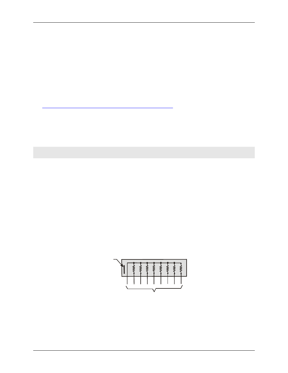
In a 2.2 K SIP, one side of each resistor connects to a single common point and brought out to a pin. The
common point is marked with a line at one end of the resistor network. A typical SIP resistor network is shown
in
Figure 3-3. SIP resistor location
2.2 K SIP
LO
I/O lines
Common
line
HI
The 6K-SSR-RACK08 has a location for installing a 2.2 K SIP resistor network (see Fi
). When
installing pull-up and pull-down resistor SIP packs, we recommend using a 2.2 K, eight-resistor SIP (MCC part
number SP-K2.29C).
3-3