Components, Components -2 – Measurement Computing 6K-SSR-RACK08 User Manual
Page 22
6K-SSR-RACK08 User's Guide
Functional Details
Components
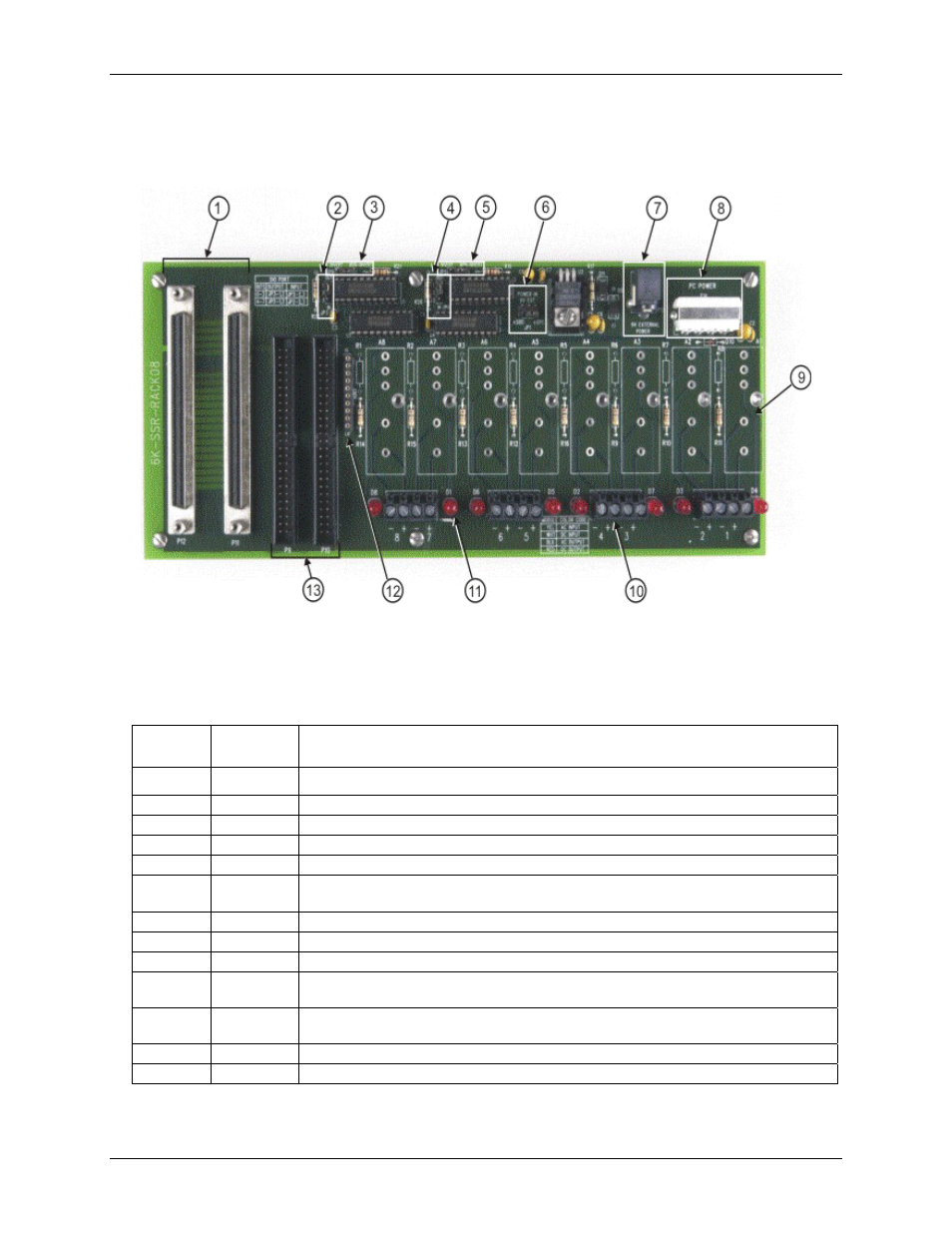
Major components on the 6K-SSR-RACK08 are shown in F
Figure 3-2. 6K-SSR-RACK08 component locations
Table 3-1. 6K-SSR-RACK08 component descriptions
Callout Board
label
Description
1
P12, P11
100-pin interface connectors. Connect to the 6000 Series control board or accessory board.
2
JP3
I/O type jumper for SSR modules 1-4.
3
JP6
Relay logic jumper for SSR modules 1-4.
4
JP2
I/O type jumper for SSR modules 5-8.
5
JP5
Relay logic jumper for SSR modules 5-8.
6 JP1 Main +5 V power jumper to select the power source — internal power from the 6000 Series
control board, external power from the computer, or external power from the AC adapter.
7
P13
External power connector. Connect to the AC adapter.
8
P14
External power connector. Connect to the computer's +5 V supply.
9
A1 to A8
Mounting locations for SSR modules <1:8>.
10
±1 to ±8
Relay screw terminals for field wiring connections. Two screw terminals are dedicated to
each SSR module.
11
D1 to D8
LEDs that indicate the status of the SSR modules. Refer to page 3-4 for a summary of the
LED states.
12
RN1
Pull-up / pull-down resistor location.
13
P9, P10
50-pin interface connectors. Connect to the 6000 Series control board or accessory board.
3-2