23 3.4 diagnostic leds, Installation – IHSE USA 437 Series DDXi DVI/VGA Extender User Manual
Page 23
INSTALLATION
23
3.4 Diagnostic LEDs
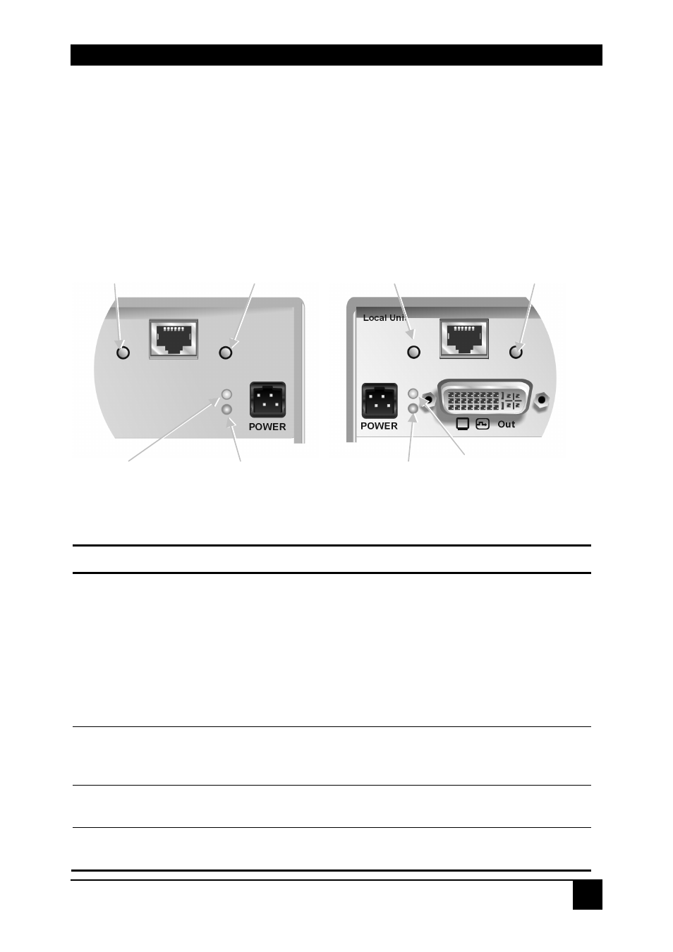
Each Extender unit is fitted with four indicator LEDs: Communication Error, Link
Status
, Device Ready and Video Signal. The Indicator LEDs are located in the same
positions on all models in the DDXI DVI/VGA KVM Extender range. The
Communication Error
and Link Status LEDs are to the left and right, respectively, of
the Interconnect sockets. The Device Ready and Video Signal LEDs are next to the
Power socket.
As an example, the location of the LEDs is shown below for K439-1W Remote and
Local units:
Communication Error
Link Status
Communication Error
Link Status
Video Signal
Device Ready
Device Ready
Video Signal
(Green)
(Red)
(Red)
(Green)
Figure 8
Diagnostic LEDs on Remote (left) and Local (right)
K439-1W units
LED
Appearance
Diagnostics
Communication
Error
Off
Flashing
slow
medium
fast
No communication error for >60 minutes
Indicates number of communication errors
during previous 60 minutes:
10-100 (CATx)
1-2
(Fiber)
100-1000(CATx)
3-10
(Fiber)
>1000 (CATx)
>10
(Fiber)
Error counter cleared automatically 60 minutes after previous communication
error.
Link Status
On
Flashing
Link connection is locked
Interconnection cable not connected or not
functioning
Device Ready
(Red LED)
Off
On
Device not ready
Device ready
Video Signal
(Green LED)
Off
On
No video signal or valid mode detected
Attached and valid mode detected