Installation – Harken HYDRO 2 Power Unit User Manual
Page 7
Hydro 2
7
Installation
While unpacking the hydraulic power unit (HPU) and electronic control box (ECB), inspect for irregularities. During transport the power
unit may have been exposed to many unusual conditions. If irregularities appear, document details and contact shipper and Harken
distributor.
Plan Installation
Mounting is required for both the HPU and the ECB. Because this installation is on a boat, the following are some points to consider
when choosing the installation location:
Location in Boat
• Dry and well-ventilated, typically near the engine room.
• HPU and ECB to be mounted within close mutual
proximity, recommended maximum 5 m wire run.
(See Electrical Installation, pg. 12)
• Provide necessary clearance for HPU.
• HPU in close proximity to battery and power supply to
reduce voltage drop. (See Electrical Installation, pg. 12)
• Provide access for maintenance and servicing. Make
access available to filler tube, filter, filter status
indicator and site gauge.
• Central to the system as illustrated in “Typical System”
diagram.
• Provide routing for hydraulic hoses from HPU to
functions. Hoses attach to manifold horizontally.
• Nearest boat’s centerline in an upright position to
reduce the heeling extremes.
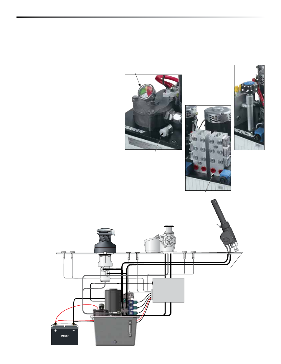
Filter status indicator
Typical System
Electronic Control
Box (ECB)
Attached manifold
Choose an area close to the plumbing center of the system
Case Drain Port
Filler tube
Hydraulic Power Unit
(HPU)