Power unit selection / parts – Harken HYDRO 2 Power Unit User Manual
Page 4
4
Hydro 2
Power Unit Selection / Parts
*One function delivers double flow output (8 gpm) using 2 motors **This number is reduced by one when a double flow function is in use.
Power
unit
Number of
functions
Max
simultaneous
functions
24v DC
Motor
Maximum
current draw
(amps)
Tank
capacity
Maximum
continuous output
Weight
Fasteners
Without manifolds
With attached manifolds
gal
l
psi@gpm bar@l/m
lb
kg
lb
kg
Hydro 1
4
1
1 x 4000 Watt
210
7.9
30 2000 @ 4 140 @ 15
89
40.5
102
46.1
M10
Hydro 2
9*
2**
2 x 4000 Watt
2 x 210
18.5 70 2000 @ 8 140 @ 30
182
82.6
194
88.2
M10
Hydro 3
15*
3**
3 x 4000 Watt
3 x 210
18.5 70 2000 @ 12 140 @ 45
233
105.9
246
111.4
M10
Power Unit Selection
Power unit selection must be based on the flow and pressure requirements for all hydraulic equipment that will operate at the same time.
Most Harken hydraulic equipment (winches, furlers, etc.) requires a flow of 4GPM/15 LPM, with a maximum operating pressure of
2000 PSI/140 BAR.
To select the correct power unit:
1. Consult the manual for each piece of hydraulic equipment that will be driven by the power unit. Note flow and pressure.
2. Determine which pieces of hydraulic equipment or circuits will be used at the same time (i.e. winch and furler).
3. Compare total flow/pressure required for each piece to table below to select power unit.
Harken Hydro Power Units are available in three sizes: Hydro 1, 2 and 3. Each motor/pump combination is rated at 4 GPM/15 LPM with a
maximum operating pressure of 2000 PSI/140 BAR.
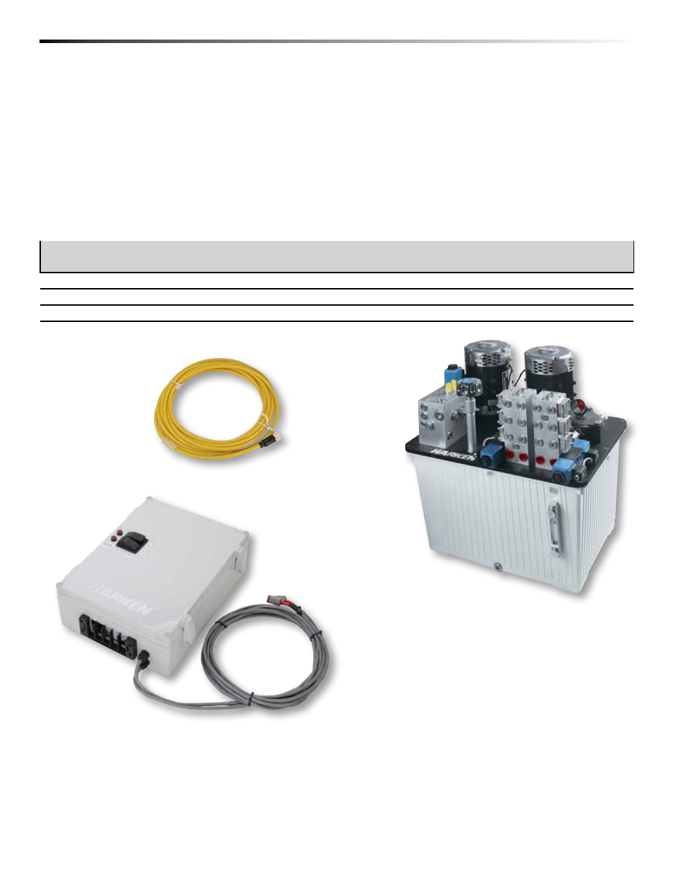
Electronic
Control Box (ECB)
Included with Unit
1. Hydraulic Power Unit (HPU)
2. Electronic Control Box (ECB)
3. Electric Wiring Cables with Terminals
2 Cables per motor to connect power unit motor to ECB
1 Cable per valve to connect power unit to ECB
Hydraulic Power
Unit (HPU)
Hydraulic Power Units
You must Supply
Suitable Hydraulic Hoses (See pg. 9)
Switches
Battery Cable with Suitable Fuses
HPU Mounting Bolts – Four (4) M10
Depth of Threaded Holes in Tank Bottom – 15 mm
ECB Mounting Bolts – Four (4) M6 or
1
/
4
"
Mounting Pad to Secure Power Unit to Boat (See pg. 11)
Hydraulic Oil (See See pg. 15)
Flow Control Valves If Required (See pg. 11)
Pressure Reducing Valves If Required (See pg. 11)
Pressure Relief Valves If Required (See pg. 11)
Wiring to Connect Valves to ECB
(1 Cable per Valve)