Start-up - blower, Pre start-up check – Greenheck MSX (470658) User Manual
Page 17
17
Modular Supply Make-Up Air Unit
®
Start-Up - Blower
Pre Start-Up Check
Rotate the fan wheel by hand and make sure no parts
are rubbing. Check the V-belt drive for proper alignment
and tension (a guide for proper belt tension and
alignment is provided in the Belt Maintenance section).
Check fasteners, set screws and locking collars on the
fan, bearings, drive, motor base, and accessories for
tightness.
1. Check the Voltage. Before starting the unit,
compare the supplied voltage, hertz, and phase with
the unit and motor’s nameplate information.
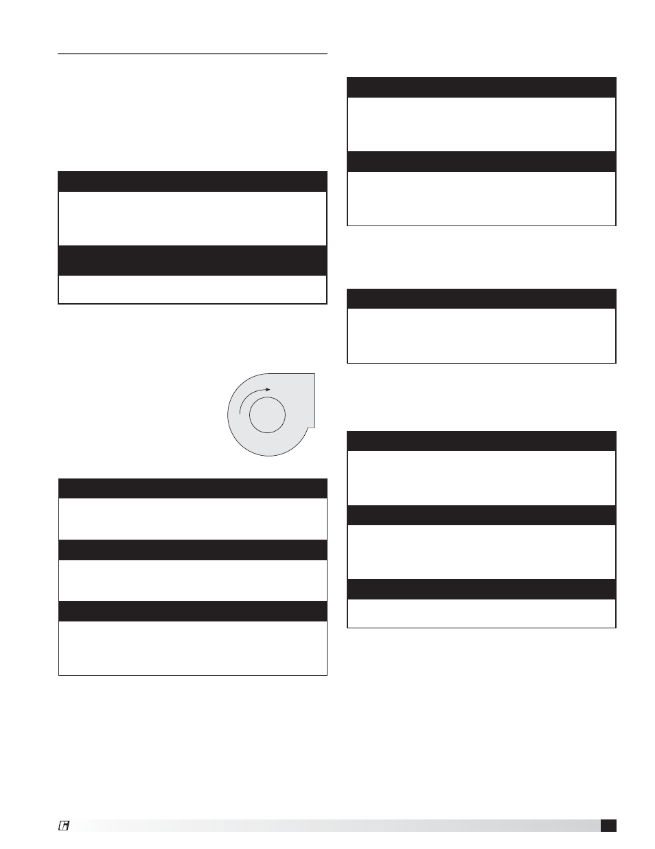
2. Check the Blower Rotation. Open the blower
access door and run the
blower momentarily to
determine the rotation.
Arrows are placed on the
blower scroll to indicate the
proper direction or reference
the example shown to the
right.
NOTE
To reverse the rotation on three phase units,
disconnect and lock-out the power, then interchange
any two power leads.
NOTE
To reverse the rotation on single phase units,
disconnect and lock-out the power, then rewire the
motor per the manufacturer’s instructions.
IMPORTANT
If the blower is rotating in the wrong direction, the unit
will move some air, but will not perform as designed.
Be sure to perform a visual inspection to guarantee
the correct blower rotation.
WARNING
Disconnect and lock-out all power and gas before
performing any maintenance or service to the unit.
Failure to due so could result in serious injury or death
and damage to equipment.
WARNING
Check the housing, blower, and ductwork for any
foreign objects before running the blower.
3. Check for Vibration. Check for unusual noise,
vibration or overheating of the bearings. Reference
the Troubleshooting section for corrective actions.
4. Motor Check. Measure the motor’s voltage, amps
and RPM. Compare to the specifications. Motor
amps can be reduced by lowering the motor RPM or
increasing system static pressure.
5. Air Volume Measurement & Check. Measure the
unit’s air volume (cfm) and compare it with it’s rated air
volume. If the measured air volume is off, adjust the
fan’s RPM by changing/adjusting the drive.
6. Set-Up Optional Components. Adjust the settings
on the optional components. See the Control Center
Layout in the Reference section for location of
optional components.
• Heating Inlet Air Sensor
Typical setting: 60-70°F (15-21°C)
• Cooling Inlet Air Sensor
Typical setting: 75°F (24°C)
• Building Freeze Protection
Typical setting: 5 minutes; 45°F (7°C)
• Dirty Filter Gauge
Typical setting: Settings vary greatly for each unit.
IMPORTANT
Excessive vibration may be experienced during
the initial start-up. Left unchecked, it can cause a
multitude of problems including structural and/or
component failure.
IMPORTANT
Generally, fan vibration and noise is transmitted
to other parts of the building by the ductwork. To
minimize this undesirable effect, the use of heavy
canvas duct connectors is recommended.
IMPORTANT
Additional starters and overloads may be provided in
the make-up air control center for optional exhaust
blowers. Any additional overloads must be checked
for proper voltage, amps and RPMs.
Blower Rotation
Blower
Housing
R
o
ta
tio
n
NOTE
The most accurate way to measure the air volume is
by using a pitot traverse method downstream of the
blower. Other methods can be used but should be
proven and accurate.
IMPORTANT
Changing the air volume can significantly increase
the motor’s amps. If the air volume is changed,
the motor’s amps must be checked to prevent
overloading the motor.
NOTE
To ensure accuracy, the dampers are to be open when
measuring the air volume.