Nozzle placement – Greenheck MSX (470658) User Manual
Page 13
13
Modular Supply Make-Up Air Unit
®
5. Mount the Remote Sensing Bulb
(by others). The expansion valve’s remote sensing
bulb should be securely strapped to the horizontal
run of the suction line at the 3 or 9 o’clock position
and insulated.
6. Check Coil Piping for Leaks. Pressurize the coil to
100 psig with dry nitrogen or other suitable gas. The
coil should be left pressurized for a minimum of 10
minutes. If the coil holds the pressure, the hook-up
can be considered leak free. If the pressure drops by
5 psig or less, re-pressurize the coil and wait another
10 minutes. If the pressure drops again, there is likely
one or more small leaks which should be located and
repaired. Pressure losses greater than 5 psig indicate
a large leak that should be isolated and repaired.
7. Evacuate and Charge the Coil. Use a vacuum
pump to evacuate the coil and any interconnecting
piping that has been open to the atmosphere.
Measure the vacuum in the piping using a micron
gauge located as far from the pump as possible.
Evacuate the coil to 500 microns or less, and then
close the valve between the pump and the system.
If the vacuum holds to 500 microns or less for
one minute, the system is ready to be charged or
refrigerant in another portion of the system can be
opened to the coil. A steady rise in microns would
indicate that moisture is still present and that the coil
should be further vacuumed until the moisture has
been removed.
IMPORTANT
Guidelines for the installation of direct expansion
cooling coils have been provided to insure proper
performance and longevity of the coils. These are
general guidelines that may have to be tailored
to meet the specific requirements of any one job.
As always, a qualified party or individual should
perform the installation and maintenance of any coil.
Protective equipment such as safety glasses, steel
toe boots and gloves are recommended during the
installation and maintenance of the coil.
IMPORTANT
All field brazing and welding should be performed
using high quality materials and an inert gas purge
(such as nitrogen) to reduce oxidation of the internal
surface of the coil.
IMPORTANT
All field piping must be self-supporting and flexible
enough to allow for the thermal expansion of the coil.
Installation of Direct Expansion (DX) Coil
Piping (optional)
1. Locate the Distributor(s) by Removing the
Distributor Access Panel
2. Verify Nozzle Placement. Inspect the refrigerant
distributor and verify
that the nozzle is in
place. The nozzle
is generally held in
place by a retaining
ring or is an integral
part of
the distributor itself.
3. Install Suction Line. Install suction line(s) from the
compressor to the suction connection(s) which are
stubbed through the side of the cabinet.
4. Install the Liquid Line and Thermal Expansion
Valve (TEV) (by others). Liquid line openings vary
by coil size and circuiting and are field supplied.
Follow the TEV recommendations for installation to
avoid damaging the valve.
Retainer
Ring
Nozzle
Distributor
Nozzle Placement
Distributor Access Panel
Distributor Location
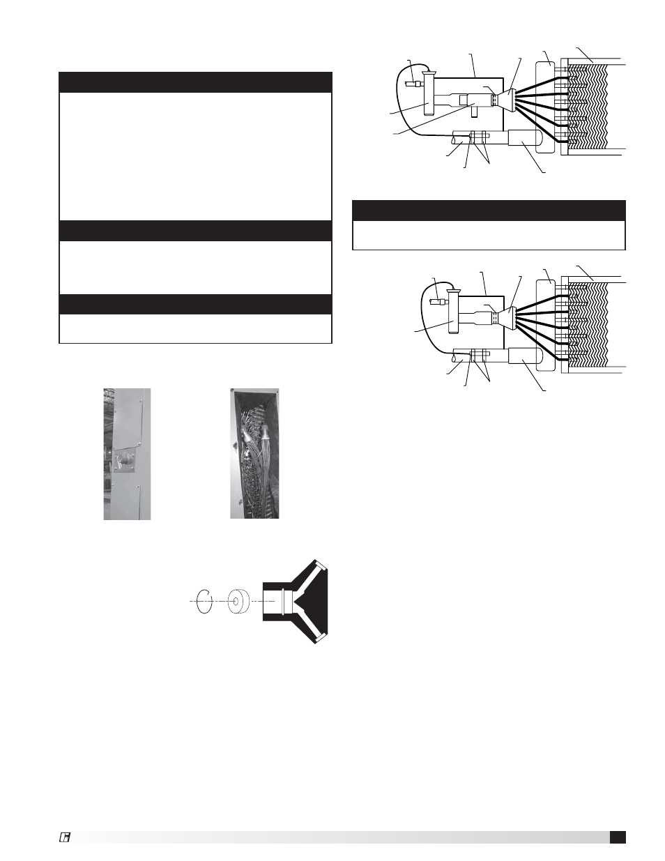
NOTE
If a hot gas bypass kit was provided by others, refer to
the manufacturer’s instructions.
General Installation
Expansion
Valve (by others)
Liquid Line
Thermal
Nozzle
Suction Header
Coil
Distributor
Suction Line
Remote Sensing Bulb
Straps
Suction Connection
Equalizer Line
Expansion
Valve (by others)
Liquid Line
Thermal
Nozzle
Suction Header
Coil
Distributor
Suction Line
Remote Sensing Bulb
Straps
Suction Connection
Hot Gas Bypass
(by others)
Equalizer Line
Installation with Hot Gas Bypass