Reference, Typical control center layout, Dirty filter switch – Greenheck DG/DGX Pilot Ignition (470651_IOM) User Manual
Page 38
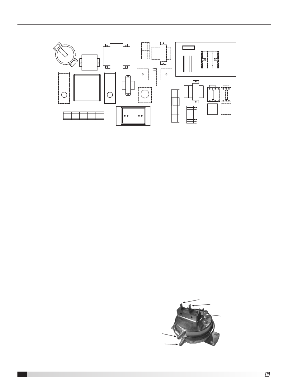
Typical Control Center Layout
Reference
13
23
22
27
29
28
20
21
4
1
7 8
2
9
3
5 16 24
17
18
19
15
14
26
10
12
11
6
25
1. Supply Motor Starter — 24 volt magnetic contacts
for starting supply motor.
2. Supply Overload — provides electronic overload
protection to supply motor.
3. Low Voltage Transformer — provides low voltage
to fan/heat/cooling enable controls.
4. Control Terminal Block — provides wiring access
to controls.
5. Fan Relay — allows power to pass to energize
motor starter.
6. High Voltage Enclosure — provides protection
from high voltage circuits.
7. Auxiliary Contact (optional) — provides one
normally closed and one normally open contact
for other equipment.
8. Exhaust Motor Starter (optional) — 24 Volt
magnetic contacts for starting exhaust motor.
9. Exhaust Overload (optional) — provides electronic
overload protection to exhaust motor.
10. Transformer Fuse (optional) — provides proper
fusing for cooling transformer.
11. Terminal Block — provides wiring access to high
voltage circuits.
12. Exhaust Fuses (optional) — provides proper fusing
for exhaust fan motor(s).
13. Dirty Filter Switch (optional) — monitors filter
pressure drop, turns on indicating light when
pressure drop is above field-adjustable set point.
14. Inlet Air Sensor (optional) — outdoor air stat that
automatically controls the heating and/or cooling
based on outdoor air temperature.
15. Remote Temperature Selector (optional) — allows
for remote temperature set point.
16. Heat Relay — allows power to pass to heating
controls.
17. Heating Terminal Block — provides wiring access
to heating controls.
18. Flame Safeguard — monitors flame, shuts down
unit when unsafe conditions are detected.
19. High Limit — prevents unit from discharging air
above a set point.
20. Low Voltage Transformer — reduces voltage to
Maxitrol system.
21. Amplifier — controls modulating valve, assures
the desired temperature is delivered.
22. Spark Generator — provides spark to ignite the
burner.
23. Transformer — provides voltage to Flame
Safeguard and optional evaporative cooling
pump.
24. Cooling Relay (optional) — allows power to pass
to cooling controls.
25. Cooling Terminal Block (optional) — provides
wiring access to cooling controls.
26. Low Voltage Transformer (optional) — reduces
voltage to cooling controls.
27. Reset Timer (optional) — resets cooling system to
run a time interval.
28. Auto Drain Relay (optional) — assures supply
pump does not operate during drain interval.
Allows pump to operate in cooling mode.
29. Cooling Timer (optional) — allows for automatic
draining of the evaporative cooling system based
on time schedule.
Dirty Filter Switch
Negative
pressure
after the
filters
Common
Normally Open
Normally Closed
CCW to decrease trip point
CW to increase trip point
Positive
pressure
before the filters
Model DG / DGX Pilot Ignition Make-Up Air
38
®