Flame signal check, Set the unit’s operating temperature – Greenheck DG/DGX Pilot Ignition (470651_IOM) User Manual
Page 18
IMPORTANT
The proper minimum firing rate setting results in a
small ribbon of continuous flame which covers the
flame rod and runs across the entire burner.
IMPORTANT
Do not allow the disconnected wire to come in
contact with a potential ground. Damage to the
amplifier or transformer could result.
IMPORTANT
On units with a burner 42 inches or greater, the
flame safeguard will automatically shut off the pilot
after the burner has been ignited.
NOTE
Adjusting the maximum and minimum firing rate
requires the inlet air sensor to be set higher than
the outdoor air temperature in order to start the
burner(s). Once high and low fire have been set,
the inlet air sensor should be set to the desired
temperature.
NOTE
Counterclockwise rotation increases the minimum
fire rate setting, clockwise rotation decreases the
setting.
9. Flame Signal Check
To measure the flame
signal connect a standard
DC voltmeter to the flame
amplifier test jacks + and
- (com) as shown to the
right. The flame signal
should be above 1.25
VDC and steady.
Check the flame signal
with the burner at pilot
only, minimum fire, mid fire and high fire. If the flame
signal is not above 1.25 VDC and steady, consult the
Troubleshooting section.
DC Voltmeter and
Flame Amplifier
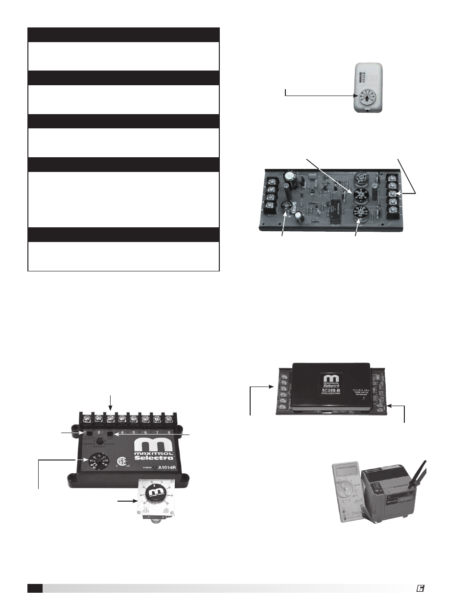
8. Set the Unit’s Operating Temperature
Set the operating temperature. The method to set the
operating temperature depends upon which Maxitrol
controller is used.
Maxitrol Series 14 - The Maxitrol Series 14 should
be set to the desired discharge temperature mode.
Place dipswitch in the “UP” position for local control
and in the “DOWN” position for remote control. Keep
LFST dipswitch in the “UP” position at all times for 10
second delay. Fig. A is required for remote control.
Maxitrol Series 44 - The Maxitrol Series 44 should
be set to the desired discharge temperature. The
temperature selector is a stand-alone dial. The stand-
alone dial may be mounted remotely.
Maxitrol Series 44 — 9 terminals
Maximum discharge
temperature setting
(Typical: 100ºF)
Minimum discharge
temperature setting
(Typical: 50ºF)
Low fire time
delay setting
(75% of maximum)
Remove wire attached
to terminal 3 to send
unit into maximum fire
Maxitrol SC25S - The SC25S is an analog signal
converter that will change a 0-10 VDC or a 4-20 mA
control signal provided by an owner-supplied Building
Management System into an output level capable of
driving the modulating gas valve.
The SC25S also limits the minimum and maximum
discharge air temperatures. Reference the unit-
specific wiring diagram and Maxitrol data sheets
included in the IOM packet.
Set the discharge temp
Typical 65°F
Minimum: Typical: 55°F
Maximum: Typical: 90°F
Fig. A
Low fire
setting
(LFST)
dipswitch
Discharge
temperature
dipswitch
Maxitrol Series 14 — 8 terminals
Remove wire attached to terminal 3
to send unit into maximum fire
Series 44 Temperature Setting
(shown as Space Temperature Control)
Set the space temperature
Typical: 70ºF
Place a jumper wire across the T1
and T2 terminals (labeled sensor)
to send the unit into maximum fire.
Remove the wire on
terminal 3 to send the
unit into minimum fire.
Model DG / DGX Pilot Ignition Make-Up Air
18
®