Accessory connector (j3) – GAI-Tronics ITA2000A ITA2000A Series Tone Remote Adapter with Scanning User and Installation Manual User Manual
Page 24
Installation
ITA2000A Series Tone Remote Adapter
03/13 20
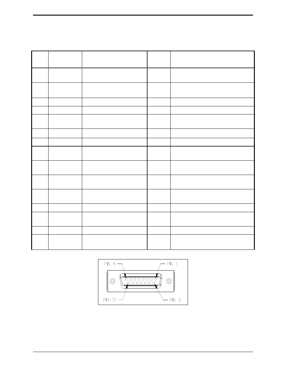
Accessory Connector (J3)
The accessory connector is located on the rear of the ITA2000A Tone Remote Adapter.
Input/Output Accessory Connector Table
Pin
Wire Color
Description
Input/
Output
Range
J3-1
Black/white
Channel Steer 3
O
JU11 B position = Lo (0 V dc)*
JU11 A position = Hi (B+)
J3-2 Blue/
white
Carrier Squelch Detect OUT
O
JU8 B position = Lo (0 V dc)*
JU8 A position = Hi (B+)
J3-3
Green
RX Audio +300 mV
RMS
O
J3-4 Black
AGND
J3-5
White/black
Channel Steer 2
O
JU12 B position = Lo (0 V dc)*
JU12 A position = Hi (B+)
J3-6 White
PTT
I Lo (0 V dc)
J3-7
Orange
RX PL Disable
O
Closure between pins 7 and 14
J3-8
Red
Channel Steer 0
O
JU14 B position = Lo (0 V dc)*
JU14 A position = Hi (B+)
J3-9
Red/white
Channel Steer 4
O
JU10 B position = Lo (0 V dc)*
JU10 A position = Hi (B+)
J3-10 Green/white CSQ
and CTCSS Detect
I
SW1-2 UP = Lo (0 V dc)*
SW1-2 DOWN = Hi (B+)
J3-11 Green/black RX
Audio
O
Connected internally to pin 4 at radio
end of cable.
J3-12 Blue
TX Audio 80 mV ac
I
J3-13 Blue/black
PTT
OUT
O
JU9 B position = Lo (0 V dc)*
JU9 A position = Hi (B+)
J3-14 Orange/black RX PL Disable
I
Closure between pins 7 and 14
J3-15 Red/black
Channel Steer 1
O
JU13 B position = Lo (0 V dc)*
JU13 A position = Hi (B+)
*default from the factory
Accessory Connector Pinout