Map panel status interface ml-116-int – FSR ML-800 User Manual
Page 44
44
ML - 800
The electrical contractor shall be responsible for the mounting of the ‘GRX-AV’ or ‘FSR-CIP’
interface and wiring to the lighting control system. The sound contractor shall be responsible for the
wiring between the Lutron interface, the ML-116-INT, and the ‘ACU’ panel as well as the system
setup to ensure proper operation.
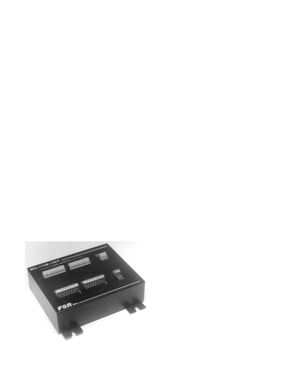
MAP PANEL STATUS INTERFACE ML-116-INT
An ML-116-INT unit can output 32 mix switch or head table switch outputs. If both mix and head
table information is required then then additional units can be added. The serial data from the ML-116
system would just loop thru each unit.
The ML-116-INT unit has an indicator LED for each corresponding wire terminal. These terminals
denote either room combinations or head table positions. The inclusion of a LED for each terminal
provides a rapid and accurate way to determine the operational status of both the ML-116 and the
LUTRON lighting equipment.
A drawing of the ballrooms/meeting rooms is provided with each system. This drawing indicates
the room mix switches and head table locations (via a numbering system) as they correspond to the
appropriate terminal positions on the ML-116-INT. If multiple ML-116-INT units are required for ei-
ther the mix or head table functions then the map drawing would indicate that and provide for it in the
numbering system.
The actual unit is 7.5" long by 6" wide by 2" high, excluding the mounting ears each of the four of
which are 1.5" wide by 0.5" long. The unit weighs approximately 3 lbs. It is located in the lighting
equipment bay, not in the audio equipment area.
The ML-116-INT is supplied with a UL listed wall mounted transformer to power the unit.
It does not matter if the ML-116-INT is powered before or after the ML-116 Audio Control Unit.
The ACU periodically scans for all line devices.
Ground To ML-116 Remote Indicator
LO
Connector
HI
Power Supply Connection no polarity
Control signals outputs