Cabling – FSR ML-800 User Manual
Page 26
26
ML - 800
CABLING
AUDIO
All audio connections to the ACU are 3 pin connectors with pin 1 shield, pin 2 High, and pin 3 Low.
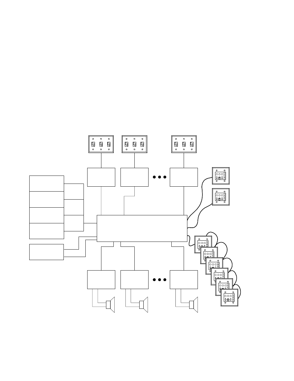
CONTROL WIRING
The following diagram illustrates the control wiring for the ML-800 system. Refer to following
sections for details on facility manager operational hookup.
Au d io in p u t p la te s
P ro v id e d b y o th e rs
B M G
S O U R C E 1
B M G
S O U R C E 2
B M G
S O U R C E 3
B M G
S O U R C E 4
P H O N E
P AG E
R o o m 1
M IX E R
R o o m 2
M IX E R
R o o m 8
M IX E R
R o o m 1
AM P
R o o m 2
AM P
R o o m 8
AM P
4 B a c k g ro u n d
M u s ic In p u ts a n d
S y s te m P a g e
H O M E R U N
E A C H
W A L L P L A T E
O R
D A IS Y C H A IN
U P T O 6
W A L L P L A T E S
M L -8 0 0
C O M B IN IN G S Y S T E M