FSR ML-800 User Manual
Page 19
ML - 800
17
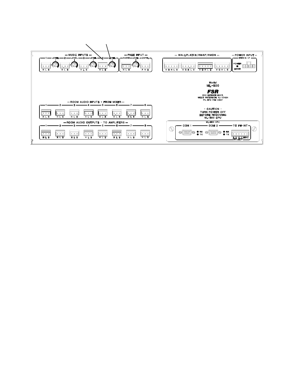
This is the main unit of the system. It routes the selected music, adjusts levels, combines rooms, handles
communication (between wallplates, map, and monitor panels), and can route audio to other ML-800s.
It also controls the paging function.
Refer to above Figure for the following discussion.
A
...These 3 pin connectors receives the audio signal from the room's mixer.
B
...These 3 pin connectors provides the audio output to the room's amplfier or EQ.
C
...These four 3 pin connectors receive the background music signals from the facility supplied sources.
The source number over each connector corresponds to the identification called out on the MAP panel
as well as the room wallplates.
D.
..This trim control provides limited volume adjustment for each background music source.
E
...This 3 pin connector accepts the page audio signal from the facilities page audio feed. A level adjust
is provided for this input. The three pin connector to the right of the level adjust is the control input for
paging. The choices are Normal or Priority, determined by an external switch.
F
...Wallplate/monitor interface connectors. These four points are where all room wallplates are con-
nected. The remote map/monitor and the ML-116-INT interface unit are connected to one of these
points. Four points are provided to ease system installation.
G
...The ML-800 regulator module accepts unregulated DC voltages from the ML-800 PSA, power
supply. A plugable connection is provided to connect to the power supply. A LED indicator is provided
to monitor the power within the unit.
H
...Facility managers panel interface connector. Refer to section on this topic for additional details.
I
....These two COM ports are for future use.
REAR OF ML-800RACK UNIT
A
B
C
D
E
F
G
H
I