FSR ML-800 User Manual
Page 27
ML - 800
27
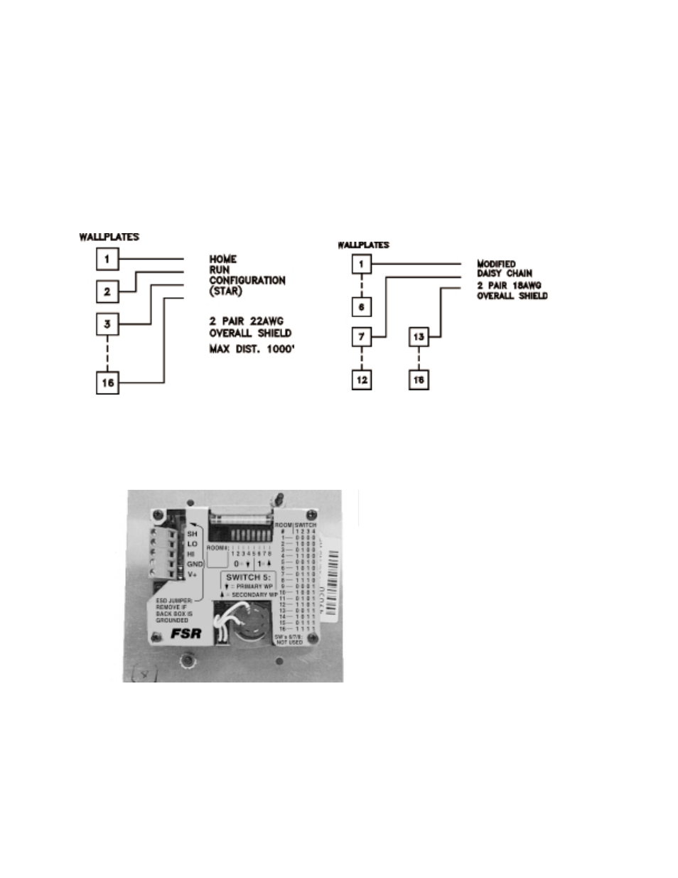
WALLPLATES
The wallplates can be wired in either a home run (star) or modified daisy chain configuration.
Use two twisted pair 22 AWG stranded, with an overall shield (West Penn # 3651) if the home run
configuration is employed for each wallplate and total distance to any wallplate does not exceed 1000
feet.
Use two twisted pair 18 AWG stranded, with an overall shield (West Penn #3751) if the wallplates are
daisy chained together (it is recommended to only daisy chain 6 wallplates per home run) with no more
than 1000' total wire length.
Refer to the figure for terminal identification. Five screw terminals are provided on the rear of the
wallplate for cable hook-up. While the Membrane wallplate is depicted all connections are identical on
the Touch wallplate.
One is installed in each room and is wired to the ML-800RACK. The wallplates mount in a standard 2
or 3 gang electrical box. An eight position dip switch on the rear of the wallplate is used to assign the
wallplate's room address. This switch is preset at the factory to the area identified on the back of the
wallplate itself, but should be checked prior to installation.
The system is shipped in a default setting for all dip switches which will permit instant operation of the
system in its usual configuration. Please refer to the DIP SWITCH section for details on all the dip
switch functions.
REAR OF WALLPLATE
Note: it is essential that in any case the voltage
on pin 1 on the wallplate connector be in excess of 8
volts DC.
TERMINAL POSITION
1 POWER 8VDC min
2 POWER GND
(THIS IS ONE PAIR)
3 DATA HIGH
4 DATA LOW
(THIS IS ONE PAIR)
5 SHIELD IF USED