Fronius IG 15 User Manual
Page 63
55
ENEN
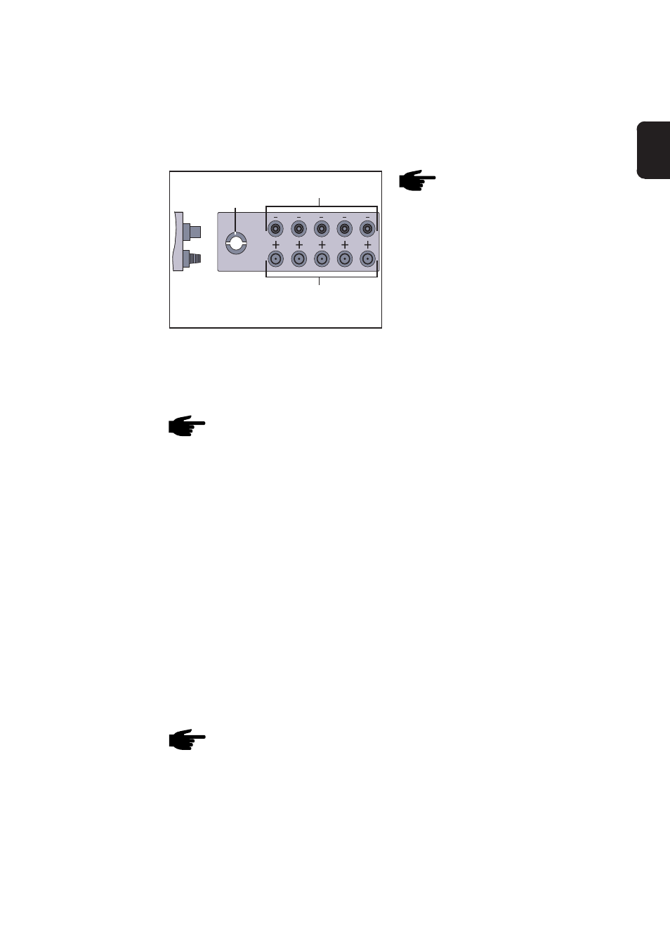
Note! When installing the
DC plugs for connection
with the solar modules,
make sure that the poles of
the solar modules correctly
correspond with the sym-
bols „+“ and „-“.
DC plug +
Connection rail with 5 pairs of plugs
Illustration also applicable for connection rail
with 1 - 5 pairs of plugs
DC sockets -
Strain relief for
connection cablel
- fix connection cable with strain relief device
- close connection area, install cover
DC plug example: multicontact plug
2. DC plug
(continued)
- install the multicontact plugs at plus and minus poles of solar module
strings
- connect the strings to the FRONIUS IG unit
Note! Never disconnect the DC plugs from the respective sockets
during power feed operation of the FRONIUS IG unit. Before
disconnecting the strings always first disconnect the mains supply
or switch the FRONIUS IG to standby operation.
Not complying with this instruction may damage the connection plugs.
Should an electric arc develop during disconnecting, both plug and socket
must be replaced. Do not re-use defective DC plugs.
To make installation and maintenance work easier, the solar modules and
the mains are connected with plugs. Depending on which version is used,
up to five pairs of DC plugs are available for connecting the solar modu-
les. Connection to the mains is effected by means of a touchproof AC
plug which can be latched.
- Fix the FRONIUS IG unit on the wall as shown in chapter „Installation“
Note! Only cables up to a cross section of 4 mm² are permitted for
the AC-plug-type connector.
3. AC plug
connection
and DC plug
- max. current at MC3 = 20 A
- max. current at MC4 = 30 A