2 layout – Foxconn Avenger User Manual
Page 12
5
1
1-2 layout
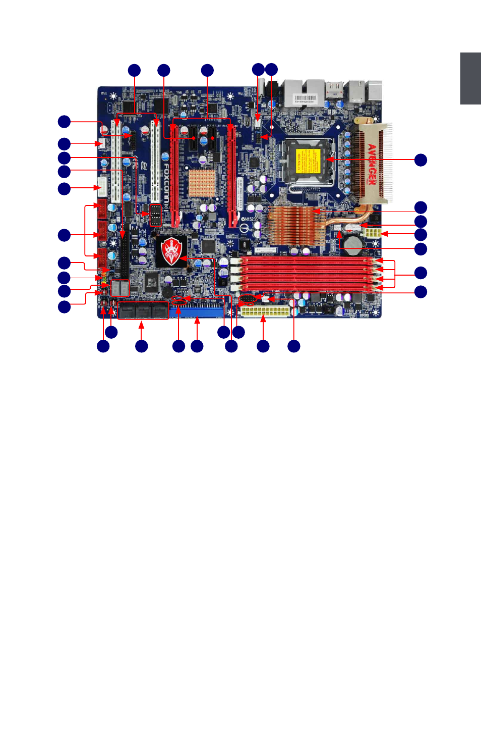
Note : The above motherboard layout is for reference only, please refer to the physical
motherboard for detail.
1. FSB Select Jumper
2. FAN1/FAN2/FAN3 Header
3. PCI Express x16 Slots
4. PCI Express x1 Slots
5. PCI Slots
6. HDA_DH Header
7. SYS_FAN Header
8. BIOS ROM 1, BIOS ROM 2
9. Floppy Connector
10. 1394a Connector
11. Front USB Connectors
12. BIOS Select Jumper
13. Front Panel Connector
14. Debug LED
15. Reset Button
16. Power on Button
17. Clear CMOS Button
18. SATA Connectors
19. Speaker Connector
20. IDE Connector
21. Clear CMOS Jumper
22. South Bridge: Intel® ICH10R
23. +5V Standby LED
24. 24-pin ATX Power Connector
25. VFD Connector
26. DDR3 DIMM Slots
27. 8-pin ATX 12V Power Connector
28. CPU_FAN Header
29. North Bridge: Intel® P45 Chipset
30. LGA 775 CPU Socket
26
28
27
29
2
30
17
18
20
24
22
16
19
21
2
23
15
8
9
11
7
10
12
13
14
1
5
2
3
4
6
25
- AHD1S-V (42 pages)
- 865PE7MF-SH (63 pages)
- 945P7AA-8EKRS2H (119 pages)
- 661FX7MF-S (64 pages)
- K7S741GXMG-6L (10 pages)
- 748K7AA-ERS (10 pages)
- NF3250GK8AA-EKRS (68 pages)
- 6100M2MA-RS2H (94 pages)
- NF4K8AB-RS (75 pages)
- K8S755M-6LRS (104 pages)
- 6497MB-S (107 pages)
- 945P7AA-8EKRS2H (106 pages)
- 755FXK8AA-ERS (108 pages)
- 760GXK8MC-RSH RAID (45 pages)
- 760GXK8MC-RSH (75 pages)
- 761GXK8MC-RSH (85 pages)
- CK804K8MA-KS (55 pages)
- NF3UK8MA-RS (70 pages)
- NF4XK8MC-RSH (68 pages)
- NFPIK8AA-8EKRS (110 pages)
- 761GXK8MB-RSH (87 pages)
- K8M890M2MA-RS2H (69 pages)
- K8T890M2AA-RS2H (62 pages)
- MCP61VM2MA-RS2HV (61 pages)
- N5VM2AA-KRS2H (2 pages)
- N570SM2AA-8EKRS2H (87 pages)
- C51XEM2AA-8EKRS2H (114 pages)
- 761MX (44 pages)
- 761GXM2MA-RS2 (65 pages)
- A6VMX (44 pages)
- A74ML Series (105 pages)
- A7VML Series (105 pages)
- A85GM (104 pages)
- A7VA-S (106 pages)
- A7VA-S (107 pages)
- M61PMP-K (111 pages)
- A7DA-S 3.0 (112 pages)
- A9DA-S (115 pages)
- Cinema II Premium (114 pages)
- A7VMX Series (106 pages)
- 720MX-K (112 pages)
- 720AL (110 pages)
- A79A-S (115 pages)
- 560A (46 pages)
- M61PMX (92 pages)