Applicable drawings, Appendix b, B.1 applicable drawings – Fluke Biomedical 956A-201-M2 User Manual
Page 93
B-1
Appendix B
APPLICABLE DRAWINGS
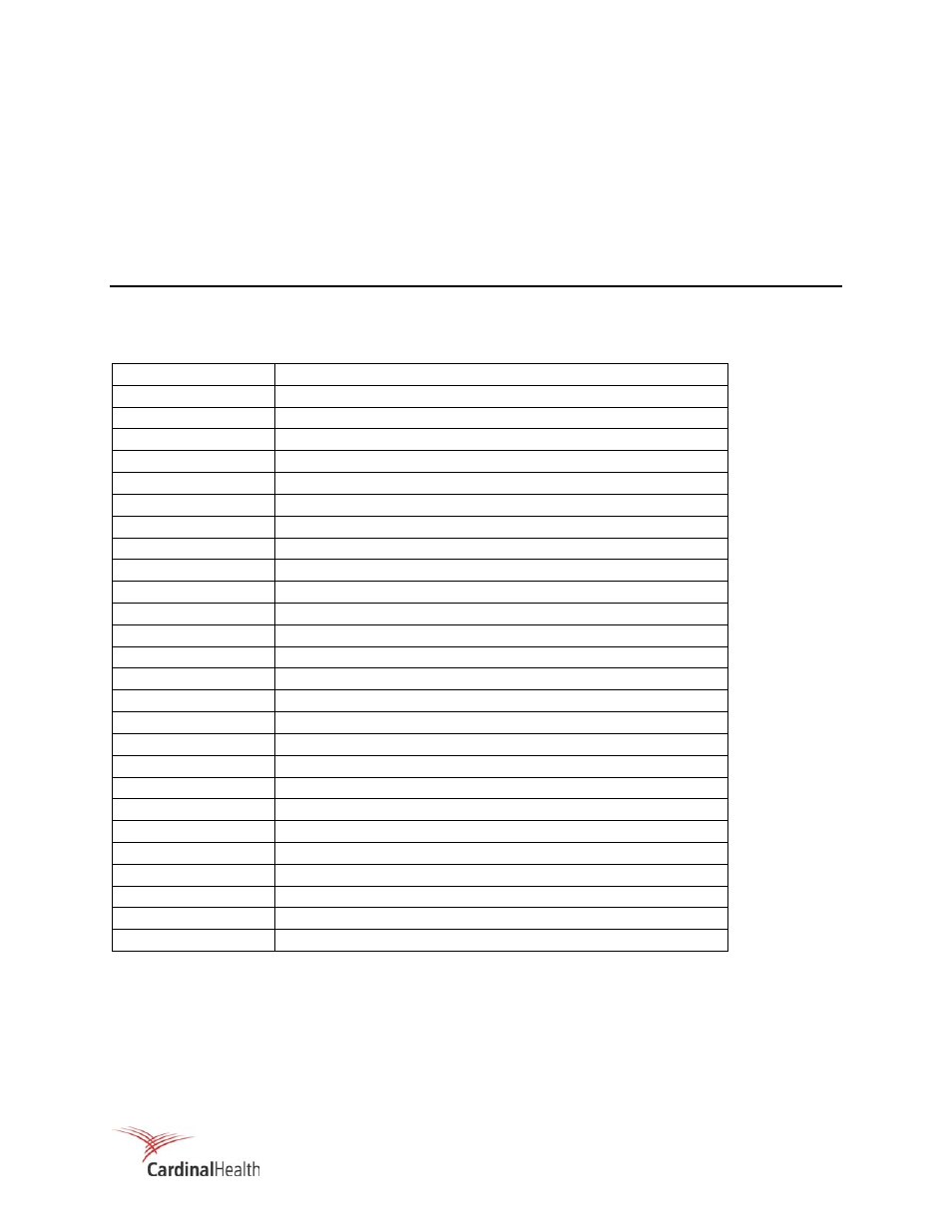
B.1 APPLICABLE DRAWINGS
Drawing No.
Description
S174014C-102
Loop Diagram, G-M
GEL897A-2X0
Detector Dimensional Outline
897A-TAB-5
Detector Main Assembly, Stainless Steel Housing
843-6-26
Wall Support, Detector
897A-210-10
PC Board Assembly
897A-210-13
Schematic, Detector
956A-201-GEL
Dimensional Outline, Readout
956A-201-M2
Assembly, Digital Readout with Trip Test
942-200-13 Schematic
Diagram
956A-100-20M2
Assembly, Front Panel with Test Pb
956-100-15M2
Assembly, Front Panel PC Board with Test Pb
942A-100-30
Assembly, Rear Panel
956A-201-55
Assembly, Power Supply
942A-100-70A
Harness Assembly
942-100-70
Assembly, Relay PC Board
942-200-50
Power Supply
956-200-10
Main PC Board Assembly
942-200-60
Assembly, High Voltage Board
942-100-35A
Harness, Power Supply
942-100-35B
Harness, Main PC Board to Relay Board
942A-100-35C
Harness, Analog output
942-100-35D
Harness, Detector Power Supply
942-100-35E
Harness, AC Power
GEL948-1
Dimensional Outline, 3-Bay Chassis
948A-2-5
Blank Panel Assembly
Gel-948-10
Panel Adapter, Dimensional Outline