Fluke Biomedical 956A-201-M2 User Manual
Page 23
2-5
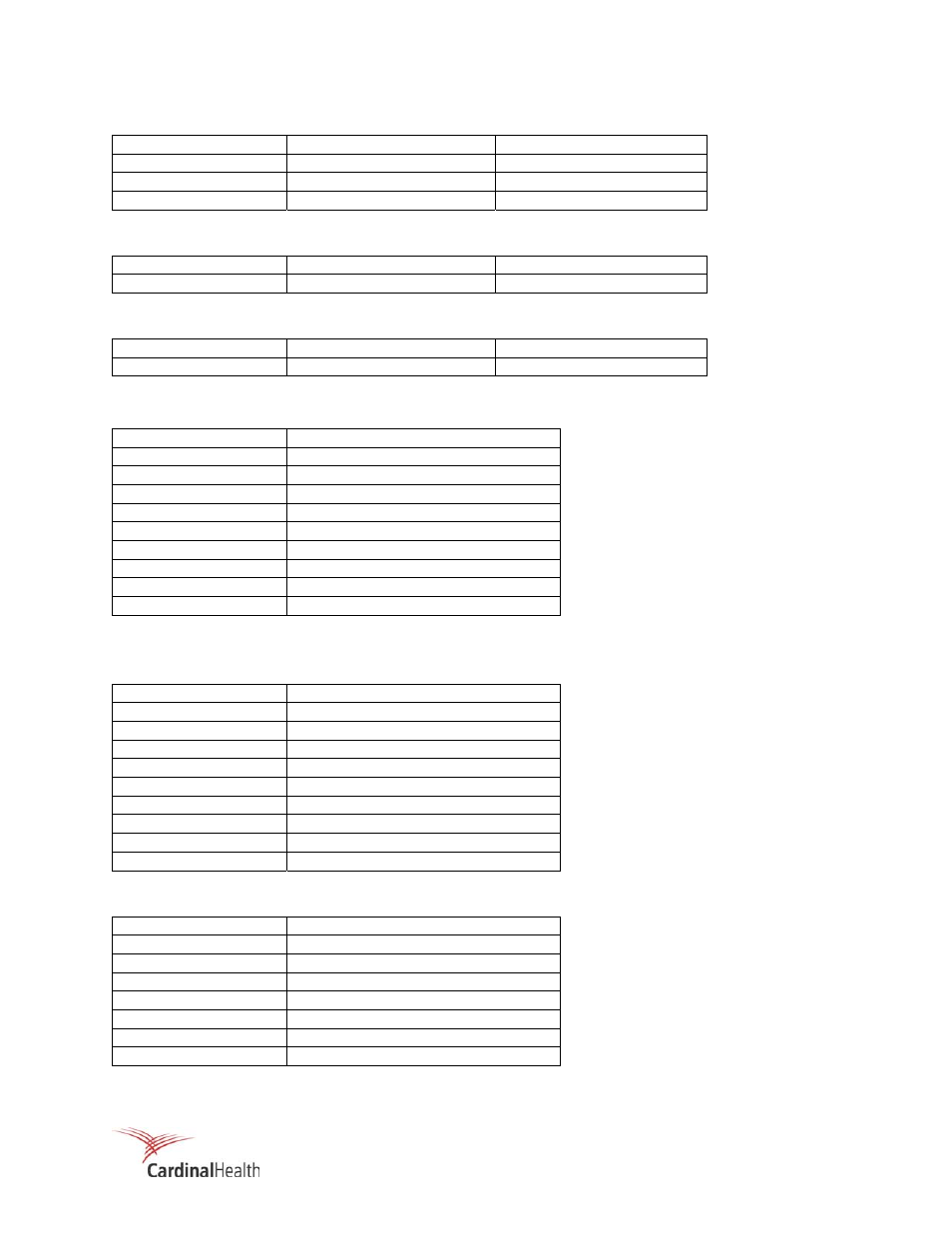
Table 2-6. Connector P3 – Power Input
Pin Signal
Internal
Connection
1
120 Vac, Line
Line fuse (F2)
2
120 Vac, Neutral
Power Supply, 120 Vac (n)
3 Safety
Ground Chassis
Table 2-7. Connector P4 – Detector High Voltage
Pin Signal
Internal
Connection
MHV
Detector High Voltage
Direct
Table 2-8. Connector P5 – Detector Signal Input
Pin Signal
Internal
Connection
BNC Detector
Signal
Direct
Table 2-9. Connector P6 – Auxiliary I/O, 956A-201-M2
Pin Signal
1
4 – 20 mA Output #1 (+)
2
4 – 20 mA Ground (-)
3
4 – 20 mA Output #2 (+)
4
4 – 20 mA Ground (-)
5
0 – 10 V* (+)
6 Ground
(-)
7
Analog Output Option (+), 0-10 mV
8 Ground
(-)
9 through 24
Not used
*0 – 10 Vdc selected for Remote Meter use on P2 (10, 11) and is not available on P6 (5, 6).
Table 2-10. Connector P7 – RS232C Option
Pin Signal
1 Protective
Ground
2 Transmit
Data
3 Receive
Data
4
Request to Send (RTS)
5
Clear to Send (CTS)
6
Data Set Ready (DSR)
7 Signal
Ground
8
Receive Line Signal Detect (DCD)
20
Data Terminal Ready
Table 2-11. 897A Detector Connection
Pin Signal
K Protective
Ground
H Check
Source
J Check
Source
E High
Voltage
MTG Screw
Chassis Ground
C
+ Voltage In
G Signal
Output