Fluke Biomedical 956A-201-M2 User Manual
Page 47
3-21
The low voltage power supply input for the preamplifier is jumper selectable. This allows the use of either
a +10 Vdc or +15 Vdc supply for detector power. If the detector is used in a 955A system, the + 15 Vdc
position is used. If the detector is used in an 855 analog area monitoring system, the + 10 Vdc position is
used. Jumper configurations are listed below.
Jumper Position Input
Voltage
J3
AB
+ 15 Vdc (factory set), digital readout
J3
BC
+ 10 Vdc, analog readout
The divide by 2 (or binary stage) converts the G-M tube pulse output into a pure square wave, at a
frequency exactly one half of the value of the input pulse frequency. This circuit provides more reliable
signal transmission to the readout electronics. The output pulse conditioning is required for use with the
diode pump circuitry used on older analog readouts. The optional jumper position, to use the detector
pulse directly (divide by 1), is provided for use with high-speed pulse counting scalers. Jumper
configurations are listed in below.
Jumper Position Divide
Option
J1, J2
AB
2, square wave output (factory set)
J1, J2
BC
1, Direct coupled
Anti-Jam Setpoint
Adjustment of the anti-jam setpoint (R41) is performed during factory calibration. If replacement of the G-
M tube is required, the detector should be returned to the factory for proper determination of the anti-jam
setpoint voltage, the dead time correction, and the count conversion factor.
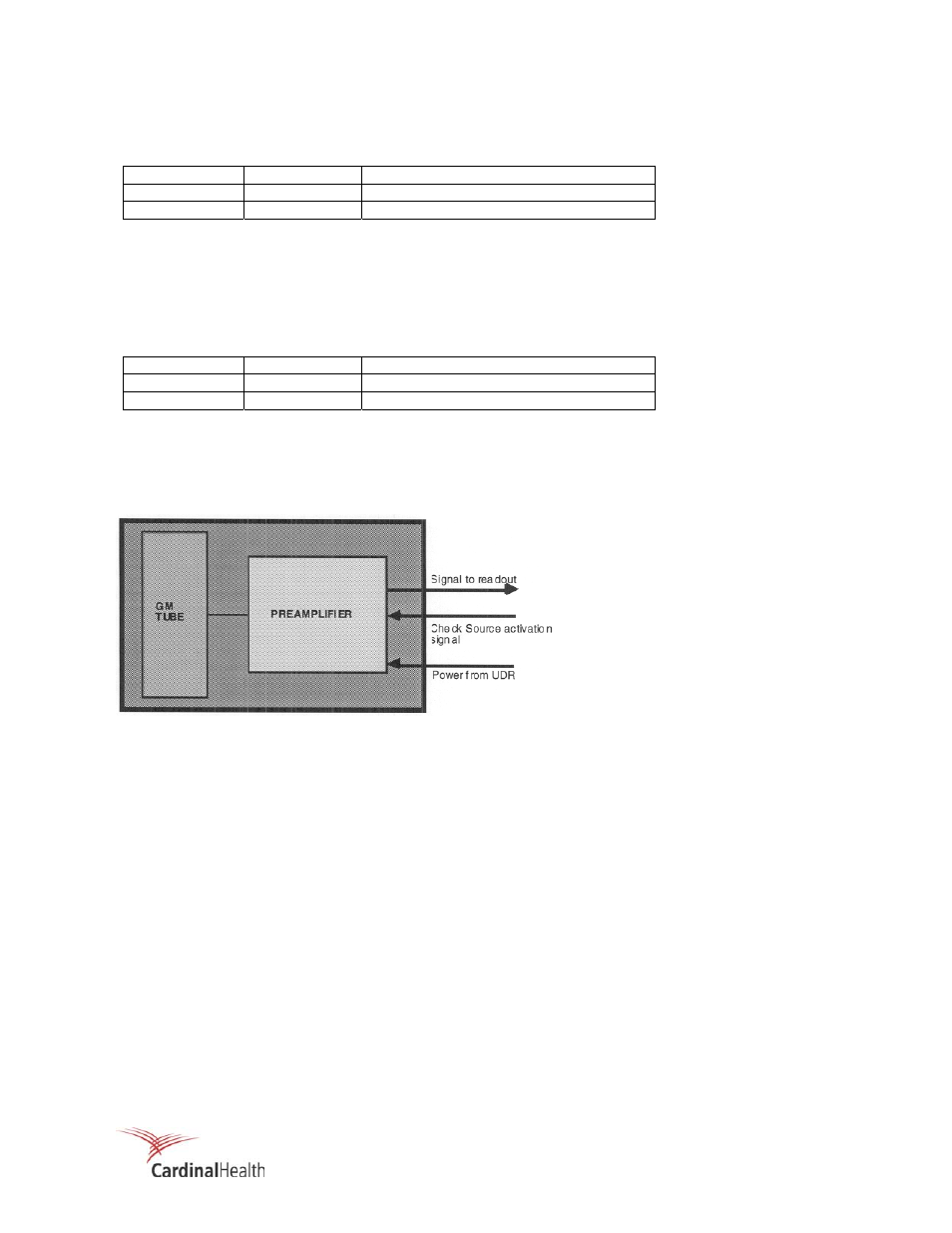
Figure 3-1. 897A Series Detector Block Diagram
Low Level Discriminator
In order to reduce electronic noise and the counting of spurious signals, an adjustable low-level
discriminator circuit is provided. To reduce the potential for radiated electromagnetic emissions from being
counted, the discriminator is factory set at 1.0 Vdc R44 is used to adjust this value.
Check Source Operation
The check source is provided to ensure that the G-M tube and the preamplifier are functional. The check
source consists of an 8-microcurie
36
CI source attached to a D'Arsonoval meter movement. Upon
actuation of the Check Source function, +15 Vdc is applied to the meter movement. This causes the
check source pan to move over the access hole in the printed circuit board, exposing the source to the
detector. The G-M tube then responds to the radioactivity present, resulting in an increase in the UDR
display. Releasing the check source pushbutton applies + 15 Vdc to the meter movement, moving the
check source to its de-activation, or rest position.
897A Series Detector Assembly