Fluke Biomedical 956A-201-M2 User Manual
Page 60
3-34
The outputs of U5 drive the latch enable pins on U50-U59 in pairs as shown in Table 3-11. U50-U59 are
BCD-to-7 segment latch/decoder/drivers. Each drives five LEDs on the bargraph, either red or green, with
the exception of U54 and U59 that drive four LEDs each. BCD to bargraph decoding is accomplished by
latching data into the appropriate device to turn on the required bargraph segments. Segment decoding is
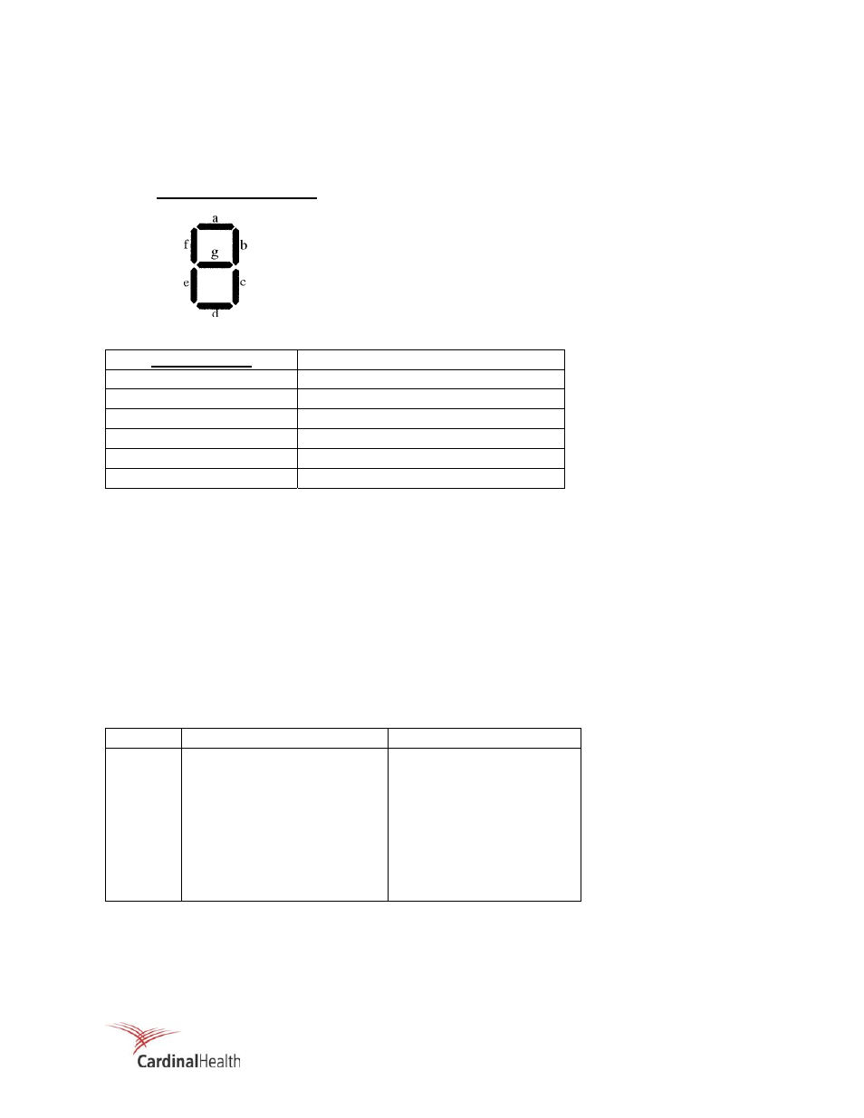
shown below:
Typical 7-Segment Digit
BCD Character
Segment(s)
1 c
7 c,
a
3 c,a,g
9
c, a, g, f
8
c, a, g, f, e
A-F None
Assume that all bargraph segments are off. Example: Write hex data 38 to bargraph address 4020. Data
38 is stored, low byte (8) in U55 and high byte (3) in U56. Data (8) in U55 causes the code for an 8 to be
output, which drives 5 output segments (c, a, g, f, e). The result is that the first five green LEDs turn on.
Data (3) in U56 causes the code for a 3 to drive segments c, a, and g connected to that device. The result
is that the first 3 of 5 segments associated with U56 will also turn on green.
Status Indicators (Write Only)
The status register (U60) is an 8-bit register with clear, and responds to address 4000. Data written into
U60 remains at the outputs until a reset occurs (/RESET), or new data is written (/STATUS INDICATORS).
Upon initial power-up, the system reset signal sets all outputs low. The status indicator write functions are
listed in Table 3-15.
Table 3-15. Status Indicator Write Functions
Data Bit
Function
Indication
D0
Check Source Indicator
D7
D1 Rate
D36
D2 Overrange
Indicator
D35
D3 Warn
Indicator
D33
D4
High Alarm Indicator
D32
D5 R/hr
Backlight
D6
D6 kR/h
Backlight
D4
D7 mR/h
Backlight
D5
U60 outputs, when high, control U61 inverter/driver to activate the appropriate front panel status
indicators. U60 outputs, when low, control U61 to deactivate the appropriate front panel status indicators.
LED 1 of 5 =
1
LED 2 of 5 =
7
LED 3 of 5 =
3
LED 4 of 5 =
9
LED 5 of 5 =
8
None =
A = F