Flowserve MX Electronic Actuator User Manual
Page 76
Limitorque MX Electronic Actuator FCD LMENIM2306-06 – 10/13
76
The ESD Time Delay Relay input (input 0) functions like any normal ESD input signal. Only if a time has been entered
into the Delay Timer value then the unit will not act on that ESD for that delayed amount of time. If the ESD signal is
removed, then the timer is canceled and will start fresh with the next assertion. You cannot change that Input 0 is ESD,
but it can be enabled/disabled, set to signal present/absent, or you can change the ESD action.
NOTE: These three inputs are kept as open-stop-close inputs. When the custom mode is enabled, the wire mode is
preset to 4-wire control and cannot be altered.
Input 3 (normal default – Stop) terminal 26
Input 4 (normal default – Open) terminal 25
Input 5 (normal default – Close) terminal 27
4.19.6 Custom Input Mode #4 - Multi-position Mode (Optional)
Custom software is available for the MX that permits the User to establish certain performance characteristics for Multi
Position controls for remote and local operations.
Input 0 (normal default - ESD) terminal 30:
• Set as enabled Ml Move To, signal present = active
Input 1 (normal default - Open Inhibit) terminal 34:
• Set as disabled, User Input, signal present = active
Input 2 (normal default - Close inhibit) terminal 35:
• Set as disabled, User Input, signal present = active
The custom input Multi Position Mode allows the user to configure up to 2 mid travel stop positions. The user will be
able to send the actuator to either of these positions in either remote or local controls. In order to use local controls in
multi-mode, that option will need to be selected in the CHANGE LOCAL Control menu. The user can select any of the
standard wire controls for inputs 3, 4, and 5 (4-wire, 3- wire Maintain, or 3-wire Inching).
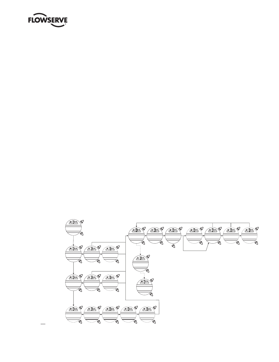
Figure 4.30 – Inputs
OFF-OK?
OFF-OK?
(OFF)
(CLOSE INHIBIT)
(OPEN INHIBIT)
(BOTH INHIBIT)
(USER INPUT)
0-1800 SECS
30 SEC INCREMENTS
See Note 4
See Note 5
See Note 6
See Note 7
ABSENT
(IGNORE)
(POSITION)
(STOP)
(OPEN)
See Note 3
NOTE 1: The custom mode will only appear if the if the custom mode option has been enabled.
NOTE 2: The "open if signal" menu will only appear, if 2-wire option is chosen. Two wire control is not
permitted if the user has modutronic or network control (DDC, FF, PB PA, PB DP, or Device Net).
NOTE 3: The number of inputs displayed for configuration will depend upon the mode selected
(standard, negative switching, or custom).
NOTE 4: ESD is hard oded for INPUT 0. You can only configure INPUTS 1 and 2 for the other options.
NOTE 5: TDR DELAY will only show for INPUT 0. All other inputs this is skipped.
NOTE 6: ESD ACTION menu will only appear if the STATUS FUNCTION for inputs is ESD otherwise
the SIGNAL PRESET menu will return to the CHANGE INPUTS menu.
NOTE 7: The ESD MOVE TO menu only appears if position is chosen as action.
NOTE 8: The user must select yes for the Save Settings menu, or the changes made in these
menus will not be saved.
NOTE 9: The SIL mode will only appear if one of the SIL modes has been enabled.
NOTE 10: Wire modes does not appear for enhanced SIL.
INPUT 0: ON, ESD Time Delay Relay, signal present, esd action closed.
INPUT 1: ON, User Input, signal present
INPUT 2: ON, User Input, signal present
INPUT 3: ON, Stop
INPUT 4: ON, Open
INPUT 5: ON, Close
See Note 1
MODE 3-WIRE INCH
MODE 2-WIRE
MODE USER INPUT
MODE 4-WIRE
See Note 2
See Note 2
See Note 8
MODE 3-WIRE INCH
MODE 2-WIRE
MODE USER INPUT
MODE 4-WIRE
CHANGE
INPUTS
STANDARD
REMOTE CONTROL
NEGATIVE
SWITCHING
MODE 3-WIRE
MAINT-OK
MODE 3-WIRE
MAINT-OK?
CHANGE
INPUT(0)?
STATUS
(ON) - OK?
STATUS FUNCTION
ESD - OK?
TDR DELAY
0 SECS - OK?
SIGNAL
(PRESENT)-OK?
SAVE
SETTINGS?
ESD ACTION
(CLOSE)-OK?
ESD MOVE TO
XXX% OPEN
OPEN IF SIGNAL
ON-OK?
CUSTOM
CONTROL
CUSTOM MODE
1-0K?
CUSTOM MODE
2-0K?
CUSTOM MODE
3-0K?
OPEN IF SIGNAL
ON-OK?
CHANGE
INPUT (5)?
YES
NO
YES
NO
YES
NO
YES
NO
YES
NO
YES
NO
YES
NO
YES
NO
YES
NO
YES
NO
YES
NO
YES
NO
YES
NO
YES
NO
YES
NO
YES
NO
YES
NO
YES
NO
CUSTOM MODE
4-0K?
YES
NO
YES
NO
YES
NO