Blower exit elbow assembly installation – DR Power Tow-Behind 9.00 Commercial (May 2006 - July 2010) User Manual
Page 22
18 DR
®
COMMERCIAL LEAF and LAWN VACUUM
Blower Exit Elbow Assembly Installation
The following procedure includes the steps necessary for
installing the Blower Exit Elbow Assembly on the DR
LEAF and LAWN VACUUM.
Connecting the Collector Box Inlet Hose to the
Blower Exit Elbow Assembly
The following procedure includes the steps necessary for
connecting the Collector Box Inlet Hose to the Blower
Exit Elbow Assembly on the DR LEAF and LAWN
VACUUM.
Blower Exit Elbow
Pull and Hook
Flexible Latches
Collector Box Hose
Hook here
Figure 15
Figure 14
Collector Box
Hose
Blower Exit Elbow
Assembly
Wing Screw
4 places
Lanyard
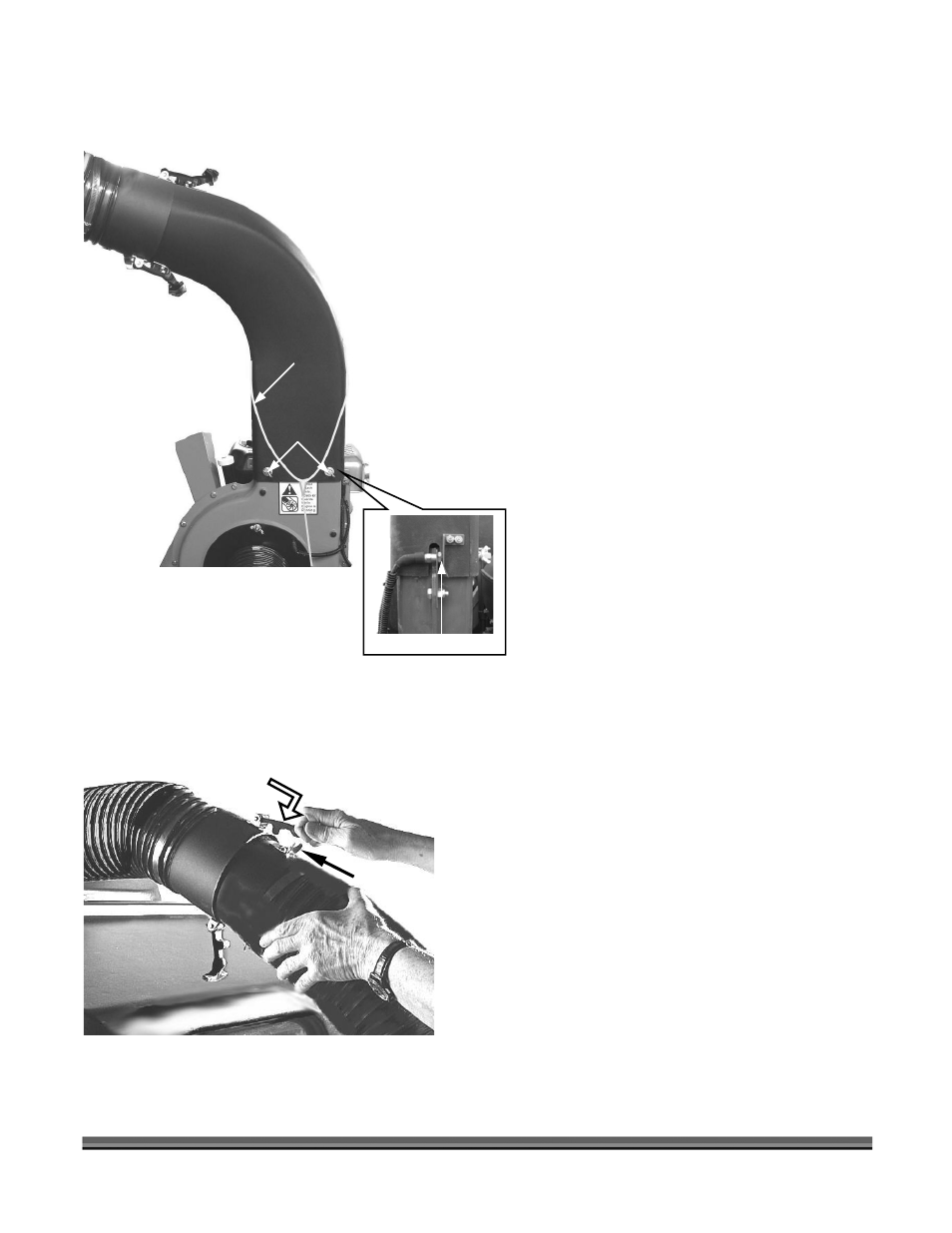
1. Install the Blower Exit Elbow Assembly on top of
the Blower Housing with the elbow pointing
toward the Collector Box (Figure 14).
2. Align the hood of the Blower Exit Elbow
Assembly to ensure that the Safety Interlock
Switch is depressed (Figure 14), verify the
position of the Lanyard as shown, and then
install a Lock Washer and Flat Washer over each
of the four (4) 5/16" x 1/2" Wing Screws and
hand tighten them to the Blower Housing
(Figure 14).
Tip: Start all four (4) Wing Screws before tightening
them securely.
1. Connect the Hose from the Collector Box to the
Blower Exit Elbow Assembly by aligning the two
(2) Flexible Latches (Figure 15) and slipping the
Hoses together.
2. Pull and hook the two (2) Flexible Latches into
place (Figure 15) to secure the Hoses.
Blower
Housing
Switch Depressed
Elbow