Gpi connection diagram, Gpis, wet/ dry configuration – DNF Controls USP-S User Manual
Page 24
Page 24 of 27
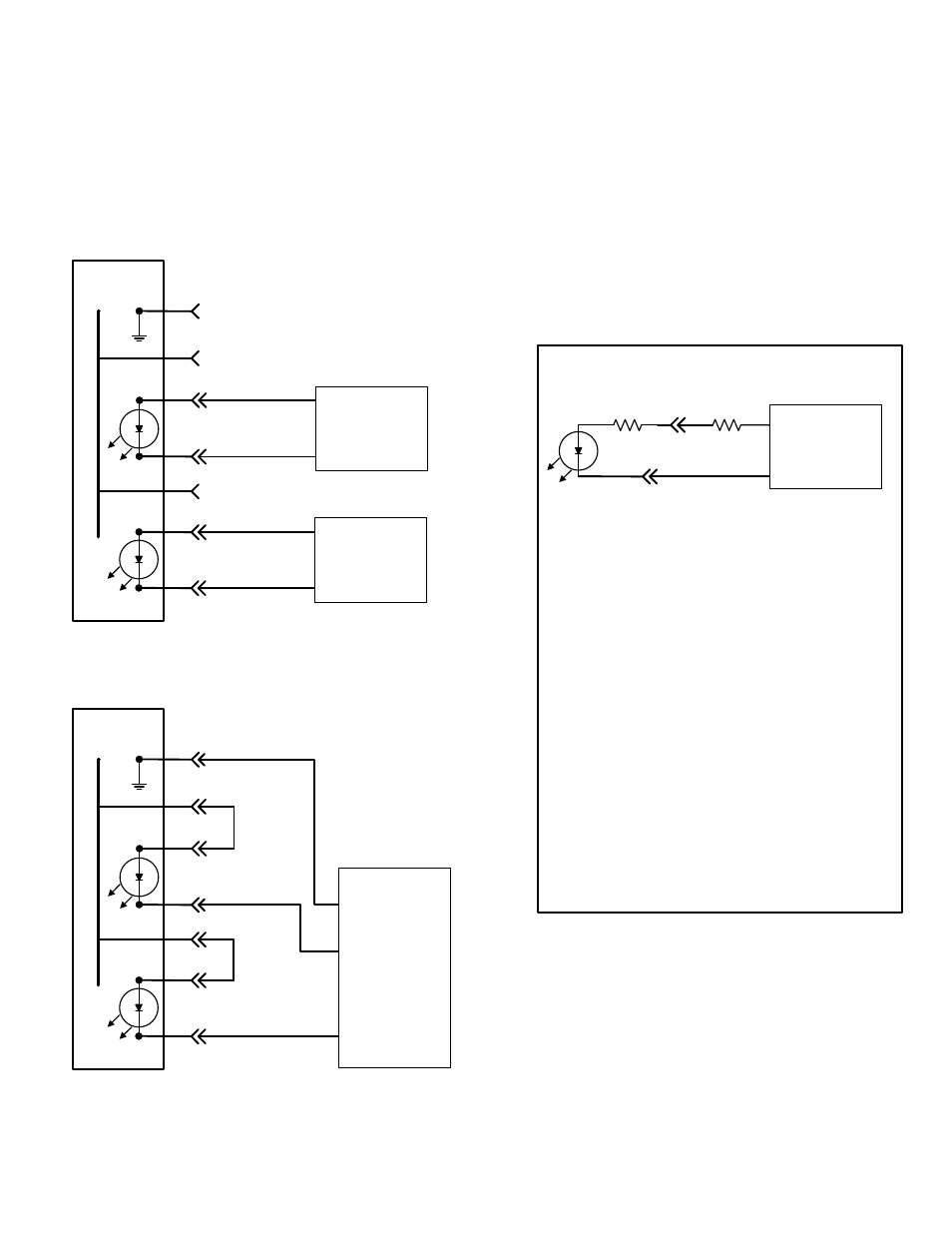
15. GPIs, WET/ DRY Configuration
EXAMPLE #1- Device Powered GPIs
EXAMPLE #2- WET GPIs using internal +5V
1
13
23
25
11
Internal +5VDC
GPI Connector
12
24
GPI #1 (+)
GPI #1 (-)
GPI #2 (+)
GPI #2 (-)
DEVICE #2
+12V
GPO #1
DEVICE #1
+5V
GPO #1
Ground
GPO
provides
path to
ground
GPO
provides
path to
ground
1
13
23
25
11
In
te
rn
al +
5V
D
C
12
24
GPI #1 (+)
GPI #1 (-)
GPI #2 (+)
GPI #2 (-)
Wire
Jumper
Wire
Jumper
DEVICE #3
GPO #1
GPO #2
Ground
GPO
provides
path to
ground
GPI Connector
Specification for GPI input:
1. Voltage: (Internal resistor only)
+3.3V minimum
+5V typical
+6V maximum
2. Current: (Internal resistor only)
5mA minimum
10mA typical
15mA maximum
For typical 10mA current, if external voltage is
higher than +5V, a series resistor is required:
R
ext
= (V
ext
- 4.5) / 0.01
V
ext
= +9V => R
ext
= 450 Ohms
V
ext
= +12V => R
ext
= 750 Ohms
V
ext
= +24V => R
ext
= 1950 Ohms
GPI Technical Data
R
Internal
330 Ohms
R
External
External
Device
Ground
Power
GPI CONNECTION DIAGRAM
- 2034CL-N (30 pages)
- 4000CL-O V3.1 (32 pages)
- 2034CL-N-PBIO (33 pages)
- 2034CL-TO (24 pages)
- 4000CL-Q (22 pages)
- 2034CL-TO-PBIO (27 pages)
- 2034CL-SX-PBIO (21 pages)
- 4000CL-SX (26 pages)
- 2034CL-MAV (22 pages)
- 2034CL-MAV-PBIO (23 pages)
- 2034CL-L Vs.3.0 (26 pages)
- 2034CL-L-PBIO VS.3.0 (28 pages)
- 4040CL_(-A, -L, -O, -NX, -7, -8, -T, -P) (43 pages)
- 2044CL-L-8 (27 pages)
- 2MCE (19 pages)
- 3040P-L_&_3040P-L-LT (20 pages)
- 3040P-L_&_3040P-L-LT (27 pages)
- 4000CL-LPH (16 pages)
- 3040P-DLO-L (39 pages)
- 4000CL-L-KBIO Vs.3.0 (21 pages)
- 4000CL-MAV70 (14 pages)
- 4000CL-N (25 pages)
- 4000CL-MAV (18 pages)
- 4000CL-TO (21 pages)
- 4000CL-AX (13 pages)
- 4040CL-EVS-PBIO (26 pages)
- Analyst, RS422/RS232 Tester (35 pages)
- Analyst, RS422/RS232 Tester with (LOG 2) VTR Data Logging Option (31 pages)
- USP3-SBX-VSS (10 pages)
- ST100-CP (6 pages)
- AnyWhere Interface Switch (20 pages)
- ST420-CP (11 pages)
- ST300-CP (13 pages)
- GTP-32 (47 pages)
- ST400-CP (19 pages)
- PBUS G and V Command Addendum (2 pages)
- CP20 (42 pages)
- DC21 (29 pages)
- DMAT-O-22 (27 pages)
- DMAT-EZ (26 pages)
- DMAT-DL (19 pages)
- DMAT-MAV (29 pages)
- DMAT-O-42 (25 pages)
- GC-32 GPIO Controller (14 pages)
- GTP-32BP Installation (2 pages)