Daktronics AB-1600-1.5,2.5 User Manual
Page 58
Maintenance & Troubleshooting
4-22
DS3
Should blink when data is received from Venus 7000
DS4
All DS4 LEDs in data distributor will light and then count
sequentially through card addresses from 0 to 15.
Output Card Miscellaneous LEDs and Switches
DS5
Power LED should be ON
S1
Board Address – Set in sequential order starting at 0.
Four output cards would be set 0, 1, 2, 3. Not 1, 2, 3, 4.
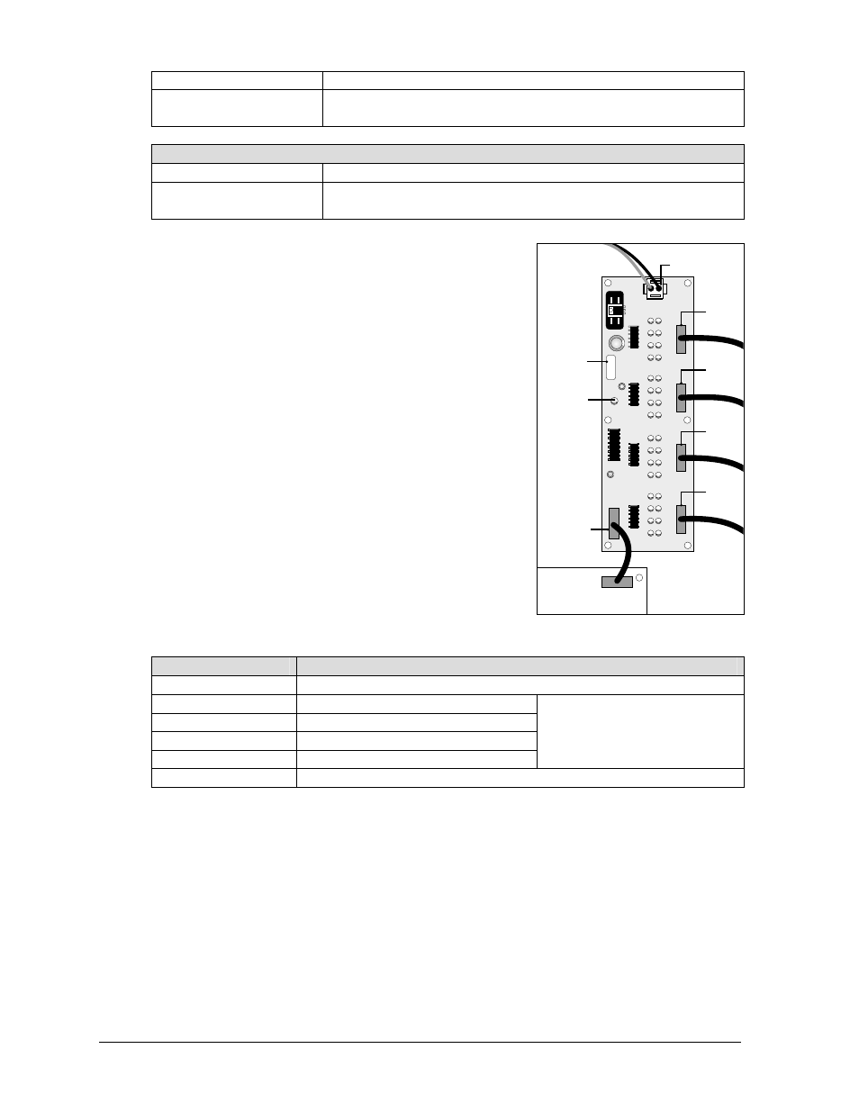
The fan controller expander board, Figure 57, is part of the data
distributor. Each of the LEDs on the fan control expander board
corresponds to a fan controller in the display. All the LEDs must be
ON for the display to operate. An OFF LED indicates a fan
controller is reporting a bad fan. At that point, check that fan
controller to determine which fan is failing.
The table below lists the connectors of the fan control expander
board along with their functions.
Connector
Function
J1
Power input from power supply
J2
Input from fan controllers 1-8
J3
Input from fan controllers 9-16
J4
Input from fan controllers 17-24
J5
Input from fan controllers 25-32
NOT EVERY DISPLAY
USES ALL INPUTS (J2-J5). ANY
UNUSED INPUTS MUST HAVE A
TERMINATOR PLUG.
J6
Output fan controller reports to J1 on receiver board
15HC1
15HC1
15HC1
15HC1
15HC1
0P-1
190-0150
SN:
3456
07-64-97
REV
.
4
Power
LED
J1 Power
Input
Receiver Board
J1
Fans
J6
Output
Circuit
Board
Label
J2
Input
J3
Input
J4
Input
J5
Input
Figure 57: Fan Controller
Expander Board