Daktronics AB-1600-1.5,2.5 User Manual
Page 33
Electrical Installation
3-13
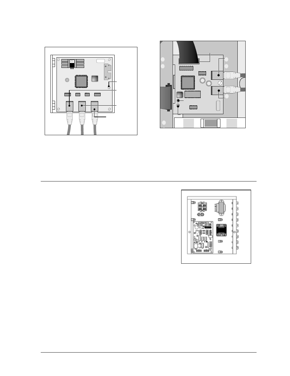
Figure 34 shows the input and output jacks on a column director.
Line controllers receive signal from the column directors and send it to the modules in a given
row and to the line controller in the next row below it. Figure 35 shows the input and output
jacks on a line controller.
3.10
Connecting the Internal Temperature Monitoring System
Figure 36 shows the inside of a fan control enclosure. Displays
with line receivers and data distributors both have fan controller
enclosures. The components in this enclosure are responsible
for monitoring the cooling fans and sending information about
the fan status to the display controller.
Refer to Section 4.12 for details and a close-up view of the
connections in the fan controller enclosure.
Connecting the Line Receiver to the Fan Controller Enclosure
In displays with a line receiver, Daktronics completes the connection from the line receiver to the
fan controller enclosure at the factory. Multiple fan controllers can interconnect together. Refer to
the System Riser Diagram in Appendix A or the System Overview Manual, if present, for
details.
J2
Column
Director
Input
J3
Line
Controller
Output
J4
Column
Director
Output
DS1
Power LED
Figure 34: Column Director
J4
Data
In
J4
Data
In
J4
Data
In
J3
Data
Out
J3
Data
Out
J3
Data
Out
DS1
Power
LED
DS1
Power
LED
DS1
Power
LED
DS2
Program
LED
DS2
Program
LED
DS2
Program
LED
J1
Data Out
J1
Data Out
J1
Data Out
Figure 35: Line Controller
Figure 36: Fan Controller Enclosure