Front cover – Daktronics AB-1600-1.5,2.5 User Manual
Page 13
Introduction
1-7
display. The receiver board receives signal from the controller computer through fiber optic cable
and distributes it to the output cards. The output cards send the signal to the display through the
column directors and line controllers. A data distributor is capable of 16.7 million-color and 64
shades of gray display images.
Line Controller: A circuit board that receives signal from a column director and distributes it to
the modules in a row. Figure 14 shows an illustration of a line controller. The line controller
mounts to the back of the left-most (front view) lampbank in each row of modules. It routes data
from the column director both down the row and to the line controller below it.
1.4 Daktronics
Nomenclature
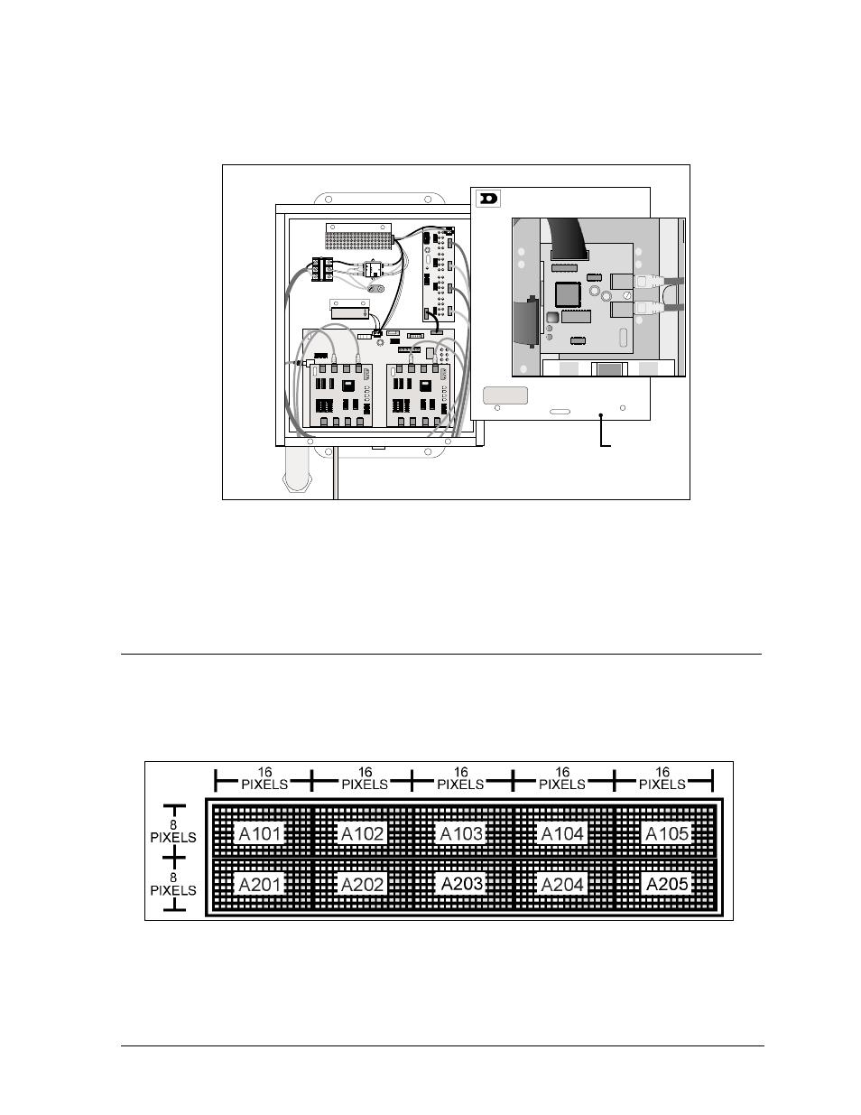
The Daktronics module numbering system assigns numbers to modules to aid in wiring and
troubleshooting. Remember, a module is two, side-by-side lens/reflector assemblies. Figure 15
illustrates how the top two rows of a large matrix display number, starting from the left. Figure 16
explains the meaning of the module numbering.
0
P
-1
1
9
0
-0
1
5
0
S
N
:
3
4
5
6
0
7
-6
4
-9
7
R
E
V
.
4
15HC1
15HC1
REV. 1
15HC1251LP
CHIPTECH
006-HC-007
1
5H
C
1
15
H
C
1
1
5H
C
1
15
H
C
1
1
5H
C
1
1
5H
C
1
1
5
H
C
1
1
5
H
C
1
1
5
H
C
1
REV. 1
15HC1251LP
CHIPTECH
006-HC-007
15H
C
1
15
H
C
1
1
5H
C
1
15H
C
1
15
H
C
1
15
H
C
1
1
5
H
C
1
1
5
H
C
1
1
5
H
C
1
0
P
-1
1
9
0
-0
1
5
0
S
N
:
3
4
5
6
0
7
-6
4
-9
7
R
E
V
.
4
0
P
-1
1
9
0
-0
1
5
0
S
N
:
3
4
5
6
0
7
-6
4
-9
7
R
E
V
.
4
1
5
H
C
1
1
5
H
C
1
1
5
H
C
1
1
5
H
C
1
1
5
H
C
1
L
IN
E
L
O
A
D
Corcom
20VB1
F-5757
6876-986
SN:985-8587
MADE
IN
MEXICO
UR
567-575
P-8678
0
P
-1
1
9
0
-0
1
5
0
S
N
:
3
4
5
6
0
7
-6
4
-9
7
R
E
V
.
4
Front
Cover
Figure 13: Data Distributor
Figure 14: Line Controller
Figure 15: Module Numbering (16x80 display) – Front View