Daktronics AB-1600-1.5,2.5 User Manual
Page 56
Maintenance & Troubleshooting
4-20
4.15
Troubleshooting the Data Distributor
If the display has a data distributor, this sub-section describes the functions of various components
within it. If the display has a line receiver, refer to Section 4.13 above. For a description of data
distributors and line receivers, refer to Section 1.3 above.
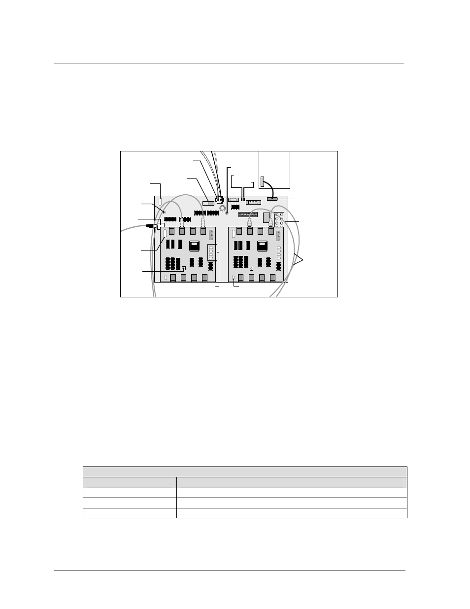
The receiver board and output cards in a data distributor work together to route display data from the
controller computer to the column director boards within the display. Figure 56 illustrates the
receiver board and outputs cards as they might appear in the data distributor.
The DS1-DS8 indicator LEDs on the receiver board must all be ON if using a fan control expander
with this display. This indicates the fan control expander board is receiving no fan failure notices
from the fan controllers.
If a fan controller expander is not used each LED corresponds to a fan controller within the display.
All must be ON for the display to operate.
If the display is out of use for 30 minutes, the receiver board sends a signal, either directly or through
the fan control expander board, to the fan controllers to turn off the fans. This design extends the life
of the fans/cooling system and electronics of the display. The fans will automatically turn back on
when the display is back in use.
The following tables list the functions of some of the connectors on the receiver board and output
cards, as well as the meanings of the diagnostic LEDs.
Receiver Board Connectors
Connector
Function
J1 (Fans)
Input from either fan controllers or fan control expander bd.
J4 (Power)
Power input from power supply
J5 (Data In)
Fiber Optic Input from controller or other equipment
15HC1
15HC1
15HC1
0P-1
190-0150
SN:
3456
07-64-97
REV
.
4
15HC1
15HC1
REV. 1
15HC1251LP
CHIPTECH
006-HC-007
15HC1
15HC1
15HC1
15HC1
15HC1
15HC1
15HC1
15HC1
15HC1
REV. 1
15HC1251LP
CHIPTECH
006-HC-007
15HC1
15HC1
15HC1
15HC1
15HC1
15HC1
15HC1
15HC1
15HC1
0P-1
190-0150
SN:
3456
07-64-97
REV
.
4
0P-1
190-0150
SN:
3456
07-64-97
REV
.
4
Fan
Control
Expander
J6
J1 Fans
J4 Power
J5 Data
In
DS1 - DS8
Indicator
LED's
DS9
Power
LED
Receiver
Board
Label
Output
Card
Label
2
2
2
2
Output Card LED's
To Column
Director
Boards
DS20
Violation
LED
1
1
1
1
Test 2
Test 1
LED
Block
Output Card
Power LED
S1 Rotary
Switch
A
A
B
B
D C D C
Figure 56: Data Distributor – Receiver Board and Output Cards