Daktronics AB-1600-1.5,2.5 User Manual
Page 57
Maintenance & Troubleshooting
4-21
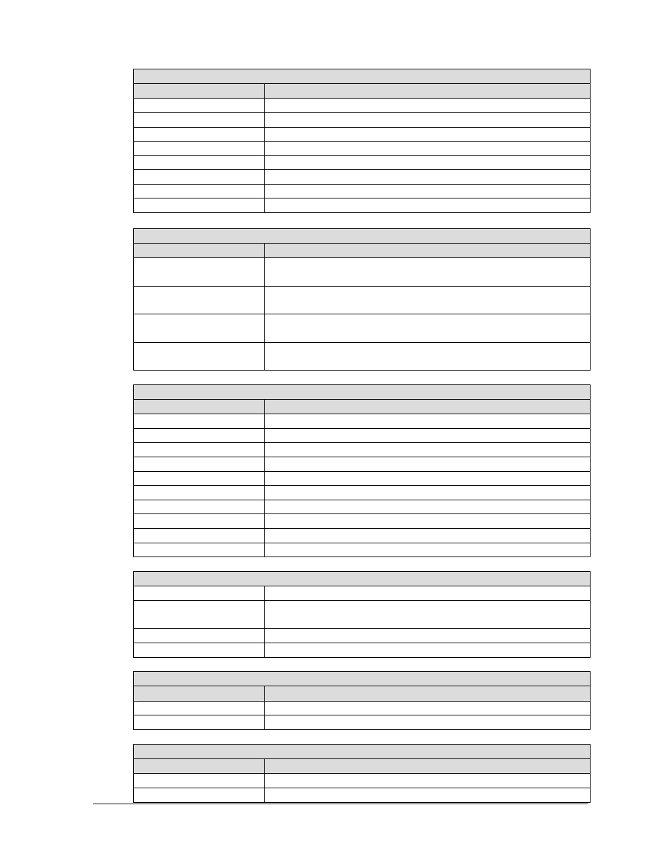
Receiver Board DS1-DS8 LEDs WITHOUT Fan Control Expander Board
LED
Function
DS1
ON if fan controller number 1 reports all fans good
DS2
ON if fan controller number 2 reports all fans good
DS3
ON if fan controller number 3 reports all fans good
DS4
ON if fan controller number 4 reports all fans good
DS5
ON if fan controller number 5 reports all fans good
DS6
ON if fan controller number 6 reports all fans good
DS7
ON if fan controller number 7 reports all fans good
DS8
ON if fan controller number 8 reports all fans good
Receiver Board DS1-DS8 LEDs WITH Fan Control Expander Board
LED
Function
DS1 & DS2
ON if fan controller expander board input J2 reports all fan
controllers good.
DS3 & DS4
ON if fan controller expander board input J3 reports all fan
controllers good.
DS5 & DS6
ON if fan controller expander board input J4 reports all fan
controllers good.
DS7 & DS8
ON if fan controller expander board input J5 reports all fan
controllers good.
Receiver Board DS10-DS19 LED Block
LED
Function
DS10 N.C.
DS11
Processor Initialization Complete
DS12
EPLD Configuration Complete
DS13 Test
Mode
DS14
Taxi Command Received (Will Flash with Data Received)
DS15
Sign is Blank
DS16
Sign Forced Blank – Signal Loss or Fan Failure
DS17
On=Fans On, Blinking=Fan Failure, Off=Fans Off
DS18 Heartbeat
DS19 N.C.
Receiver Board Miscellaneous LEDs and Jumpers
DS9
Power LED should be ON
DS20
Violation LED – If ON indicates a problem with signal
format or configuration
W1
Jumper – Test Pattern, Bottom=ON / Top=OFF
W2
Jumper – Fan Sensing, Top=Enable / Bottom=Disable
Output Card Connectors
Connector
Function
J2, J3, J6, J7
Data 1 Output – All connectors XMIT same data
J4, J5, J8, J9
Data 2 Output – All connectors XMIT same data
Output Card DS1-DS4 Indicator LEDs
LED
Function
DS1
Should blink when data is received from Venus 7000
DS2
Should blink when data is received from Venus 7000