Power supplies, Light detector, Modem – Daktronics AF-3165-34-RGB User Manual
Page 44: Figure 36: modem
Maintenance and Troubleshooting
40
Power Supplies
The LED power supplies are identified as assemblies 0A-1241-4001 in the component location
drawings.
Complete the following steps to remove a power supply from the display:
1.
Remove the module directly in front of the failed power supply.
2.
Disconnect and label all the wires connected to the power supply.
3.
Remove the hardware holding the power supply in place to free the unit.
4.
Follow these steps in reverse order to install a new power supply. Refer to the display’s
Schematic when reconnecting the wires.
Light Detector
The light detector is internally mounted and wired at Daktronics. It is located in the bottom left corner
on the front of the display (identified as assembly 0A-1241-4013 (LT) in the Component Layout
Diagram). A 4-conductor cable connects the light detector to the signal termination panel. The cable is
terminated at the terminal block on the light sensor and at the signal termination panel (refer to your
display’s schematic). When the displays are mounted back-to-back, only one side has a light sensor.
Light Detector
Pin No.
(TB1)
Cable Wires
Color
1
Red
2
Green
3
White
4
Black
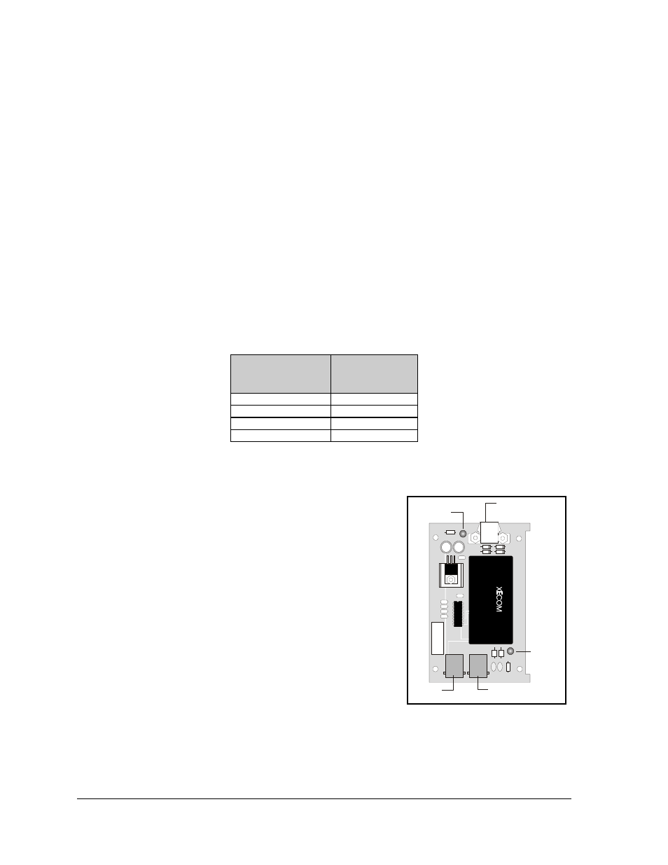
Modem
If a modem was included with the display, it is located inside
the display next to the controller board.
1. To replace a modem, first disconnect the power and
signal connections (refer to Figure 36 on the right for
the location of the power jack).
2. The modem is held in place with four screws. Remove
the screws and lift the modem out of the display.
3. Attach the new modem using the same four screws
removed in step 2, above.
The modem module has two LEDs. The Power LED should
remain lit while power is applied to the modem. The Active
LED will light when the modem is in the process of
communicating.
A modem system requires a jumper to be set on the
controller board.
RS/232
OUT
J1 Phone
IN
Active
LED
Power
LED
Power
Connection
Figure 36: Modem